|
Microduino USBHOST mainly supply the USB host function for some equipment, supports USB host controller and USB peripherals, such as mobile phones OTG function, keyboards, joystick, and camera.
Features
- Support MicroUSB interface;
- Small, cheap, stackable, opened platfrom;
- Open source hardware circuit design, compatible with the Arduino IDE development environment for programming;
- Define unified interface Microduino specification and contain rich peripheral modules. Set up the quick connection with other Microduino modules and sensors easily and flexibly.
- 2.54 pitch row female connector for easy integration into breadboard.
Specifications
- Electrical specifications
- 3.3V or 5V power;
- USB host uses power protocol of 5V/500mA;
- Using TC74HC4050 level conversion chip, provides the high anti-interference and stable output;
- D+, D- and VBCOMP has ESD protection function;
- The firmware/hardware control internal D+ pull up resistors (peripherals mode) and D+/D- pull down resistor (host mode);
- Communication
- Compatible with the MAX3420E USB peripheral which has the SPI interface;
- Comply with USB 2.0 specification (12 Mbps peripherals at full speed, full speed/low speed 12Mbps/1.5 Mbps host);
- Smart USB SIE;
- Automatic processing of USB flow control and double buffer;
- Process low level USB signaling.
- Supported devices:
- HID devices, such as keyboards, mouse, joystick and so on;
- Game controller - Sony PS3,Nintendo Wii,XBOX360;
- USB-to-serial converter - FTDI,PL-2303,ACM,mobile phones with OTG function and GPS receiver;
- Android mobile with ADK function;
- Digital Camera - Canon EOS's Powershot, Nikon digital SLR cameras and P&S, and general PTP;
- Mass storage devices, such as U disk, card reader, external hard drive;
- Bluetooth dongle.
| Chip Pin |
Microduino Pin |
Function
|
| RES |
RST |
reset chip
|
| SCLK |
D13 |
SPI serial clock input
|
| SS |
D5 |
SPI slave select input
|
| MISO |
D12 |
SPI serial data output
|
| MOSI |
D11 |
SPI serial data input
|
| INT |
D4 |
Interrupt output
|
 Microduino-USBHOST-Pinout Document
Eagle PCB local download
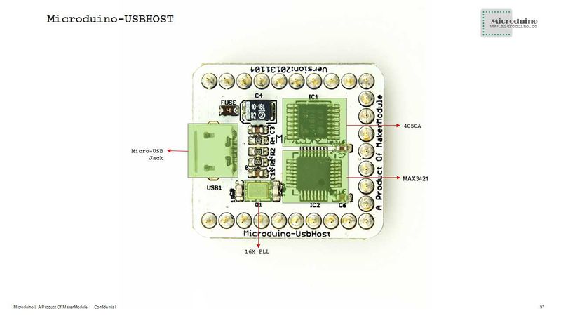
Main components:
Development
- Need library: https://github.com/felis/USB_Host_Shield_2.0
- Serial debug is disabled under default condition.
- You need open the file "settings.h" from library folder;
- Find “#define ENABLE_UHS_DEBUGGING 1”, an then change to “#define ENABLE_UHS_DEBUGGING 1”, then save it.
- USB_Host_Shield_2.0 library usage:
An ordinary Bluetooth adapter. You can easily add different Bluetooth services, such as a PS3 or Wii controller or SPP which is supported through Bluetooth virtual serial port. A number of different examples can be found in the examples directory.
Connect USB peripherals. Such as a mouse, handle etc.
Connect HID devices via Bluetooth, currently supports HID mouse and keyboard.
Allow you send data to your Microduino from PM/mobile phone via Bluetooth.
Allow you to use the Sony PS4 controller via Bluetooth and USB.
Use DUALSHOCK3, navigation or motion controller via Bluetooth and USB.
- Xbox Libraries:
- Xbox Libraries:
The library uses USB as the Xbox 360 controller.
Application
Light a LED via a mobile using the ADK example library:
Prepare work
- Prepared hardware:Microduino FT232R, Microduino Core, Microduino USBHOST, OTG cable, make sure your Android device supports and turn on the USB debug mode, USB cable;
- Prepared software:USB_Host_Shield_2.0 library, Arduino IDE(1.0 release and upper);
- Uncompress the zip folder and rename to “USB_Host_Shield” becasue Arduino IDE doesn't support any special characters, then copy to libraries folder of Arduino IDE;
- Connect the Microduino FT232R and PC using USB cable to download program and serial monitor;
- Connect a LED to I/O port D6 of Microduino-Core;
Debug
- Open the example program "ArduinoBlinkLED" from ADK folder of examples;
- Change LED_BUILTIN to Microduino pin in "#define LED LED_BUILTIN", such as "#define LED 6". But can't be D13, because D13 is used as SCK.
- After compiled, select the board "Microduino Core (Atmega328P@16M,5V)", download directly;
- Connect the mobile phone and Microduino USBHOST by OTG cable and USB cable;
- Open the serail monitor, will display "Arduino Blink LED Started";
- The phone will automatically pop up the application "ArduinoBlinkLED", download and install it;
- After installed the application, will prompte to open the USB connection fittings, and click OK to enter the program interface;
- Successful connection will show "connected", and can control the LED light on and off via the button.
Bug
History
Picture
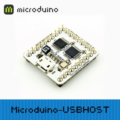
Front
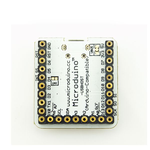
Back
Video
|


