Difference between revisions of "Main Page"
From Microduino Wiki
(→Microduino Extension Modules) |
|||
| Line 46: | Line 46: | ||
{| style="width: 800px;" | {| style="width: 800px;" | ||
| colspan="2" | | | colspan="2" | | ||
| − | ==Microduino | + | |
| + | ==Microduino Upin27 Series== | ||
|- | |- | ||
| | | | ||
| − | '''[[Microduino | + | |
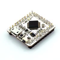
| − | * | + | [[file:Microduino-core+ -rect.jpg|200px|left]] |
| − | + | ||
| − | *Compatible | + | |
| − | * | + | | |
| − | + | *'''[[Microduino AVR core module series(Arduino Compatible)]]''' | |
| + | *'''[[Microduino Getting start]]''' | ||
| + | *'''[[Microduino (Arduino Compatible Board)Tutorial]]''' | ||
| + | *'''[[The solution for FT232R (USBTTL) error "FT232R USB UART"]]''' | ||
| + | |||
| + | |||
|- | |- | ||
| | | | ||
| − | |||
| − | |||
| − | |||
| − | |||
| − | |||
| − | |||
| − | |||
| − | | | + | [[file:Microduino- CoreSTM32 -rect.jpg|200px|left]] |
| + | |||
| + | |||
| | | | ||
| − | '''[[Microduino | + | *'''[[Microduino STM32 core(STM32 Compatible)]]''' |
| − | * | + | |
| − | + | *'''[[Microduino STM32 Getting start]]''' | |
| − | * | + | |
| − | + | *'''[[Microduino CoreSTM32 Tutorial]]''' | |
| − | + | ||
|- | |- | ||
| | | | ||
| − | |||
| − | |||
| − | |||
| − | |||
| − | |||
| − | |||
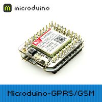
| + | [[file:Microduino-GPRS-rect.jpg|200px|left]] | ||
| − | |||
| − | |||
| − | |||
| − | |||
| − | |||
| − | |||
| | | | ||
| − | '''[[Microduino | + | |
| − | + | *'''[[Microduino Extension Modules(Upin27 Compatible)]]''' | |
| − | + | ||
| − | |||
| − | |||
|- | |- | ||
| | | | ||
| − | |||
| − | |||
| − | |||
| − | |||
| − | |||
| − | + | ||
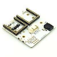
| − | + | [[file:Microduino-Station-rect.jpg|200px|left]] | |
| − | |||
| − | |||
| − | |||
| − | |||
| − | |||
| − | |||
| − | |||
| − | |||
| − | |||
| − | |||
| − | |||
| − | |||
| − | |||
| − | |||
| − | |||
| − | |||
| − | |||
| − | |||
| − | |||
| − | |||
| − | |||
| − | |||
| − | |||
| − | |||
| − | |||
| − | |||
| − | |||
| − | |||
| − | |||
| − | |||
| − | |||
| − | |||
| − | |||
| − | |||
| − | |||
| − | |||
| − | |||
| − | |||
| − | |||
| − | |||
| − | |||
| − | |||
| − | |||
| − | |||
| − | |||
| − | |||
| − | |||
| − | |||
| − | |||
| − | |||
| − | |||
| − | |||
| − | |||
| − | |||
| − | |||
| − | |||
| − | |||
| − | |||
| − | |||
| − | |||
| − | |||
| − | |||
| − | |||
| − | |||
| − | |||
| − | |||
| − | |||
| − | |||
| − | |||
| − | |||
| − | |||
| − | |||
| − | |||
| − | |||
| − | |||
| − | |||
| − | |||
| − | |||
| − | |||
| − | |||
| − | |||
| − | |||
| − | |||
| − | |||
| − | |||
| − | |||
| − | |||
| − | |||
| − | |||
| − | |||
| − | |||
| − | |||
| − | |||
| − | |||
| − | |||
| − | |||
| − | |||
| − | |||
| − | |||
| − | |||
| − | |||
| − | |||
| − | |||
| − | |||
| − | |||
| | | | ||
| − | '''[[Microduino | + | *'''[[Microduino Extension Board(Upin27 Compatible)]]''' |
| − | |||
| − | |||
| − | |||
| − | |||
| − | |||
|- | |- | ||
| | | | ||
| − | |||
| − | |||
| − | |||
| − | |||
| − | |||
| − | |||
| − | |||
| − | |||
| − | |||
| − | |||
| − | |||
| − | |||
| − | |||
| − | |||
| + | |} | ||
| + | <br> | ||
| + | <br> | ||
| + | {| style="width: 800px;" | ||
| + | | colspan="2" | | ||
| + | ==Microduino Hpin52 Series== | ||
|- | |- | ||
| | | | ||
| − | |||
| − | |||
| − | |||
| − | |||
| − | |||
| − | |||
| − | + | [[file:MicroWRT.jpg|200px|left]] | |
| − | |||
| − | |||
| − | |||
| − | |||
| − | |||
| − | |||
| − | |||
| − | |||
| − | |||
| − | |||
| − | |||
| − | |||
| − | |||
| − | |||
| | | | ||
| − | |||
| − | |||
| − | |||
| − | |||
| − | |||
| + | *'''[[MicroWRT Series(OpenWRTCompatible)]]''' | ||
| + | *'''[[MicroWRT Getting start]]''' | ||
| + | *'''[[MicroWRT (OpenWRT Compatible Board)Tutorial]]''' | ||
|- | |- | ||
| | | | ||
| − | |||
| − | |||
| − | |||
| − | |||
| − | |||
| − | |||
| − | |||
| − | |||
|} | |} | ||
| − | + | <br> | |
| − | + | <br> | |
{| style="width: 800px;" | {| style="width: 800px;" | ||
| colspan="2" | | | colspan="2" | | ||
| − | ==Microduino | + | |
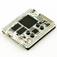
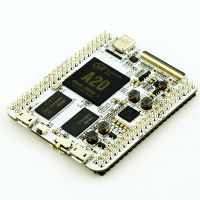
| + | ==Microduino HPin88 Series== | ||
|- | |- | ||
| | | | ||
| − | + | ||
| − | + | [[file:MicroCookie-Zen-rect.jpg|200px|left]] | |
| − | + | ||
| − | + | ||
| | | | ||
| + | *'''[[MicroCookie FPGA Series(Compatible 7Z020 of FPGA + ARM Architecture)]]''' | ||
| + | *'''[[MicroCookie-Zen Getting start]]''' | ||
| + | *'''[[MicroCookie-Zen Application Tutorial]]''' | ||
|- | |- | ||
| | | | ||
| − | |||
| − | |||
| − | |||
| − | + | [[file:MicroCookie-Nux-rect.jpg|200px|left]] | |
| − | |||
| − | |||
| − | |||
| − | |||
| − | |||
| − | |||
| − | |||
| | | | ||
| − | '''[[ | + | *'''[[MicroCookie ARM Cortex Series(Compatible ARM Cortex A7 Architecture)]]''' |
| − | * | + | *'''[[MicroCookie-Nux Getting start]]''' |
| − | * | + | *'''[[MicroCookie-Nux Application Tutorial]]''' |
| − | |||
| − | |||
| − | |||
|- | |- | ||
| | | | ||
| − | |||
| − | |||
| − | |||
| − | |||
|} | |} | ||
| − | |||
<br> | <br> | ||
<br> | <br> | ||
| − | |||
{| style="width: 800px;" | {| style="width: 800px;" | ||
| colspan="2" | | | colspan="2" | | ||
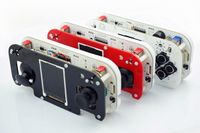
| − | ==Microduino | + | ==Microduino Game machine&Controller series== |
|- | |- | ||
| | | | ||
| − | |||
| − | |||
| − | |||
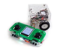
| − | + | [[File:Microduino-Joypad.jpg|200px|left]] | |
| − | |||
| − | |||
| − | |||
| − | |||
| − | |||
| − | |||
| − | |||
| | | | ||
| − | '''[[Microduino- | + | *'''[[Microduino-Joypad]]''' |
| − | * | + | *'''[[Microduino-Joypad Getting start]]''' |
| − | * | + | *'''[[Microduino-Joypad Application Tutorial]]''' |
| − | |||
| − | |||
|- | |- | ||
| | | | ||
| − | |||
|} | |} | ||
| Line 376: | Line 183: | ||
| colspan="2" | | | colspan="2" | | ||
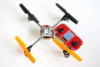
| − | ==Microduino | + | ==Microduino Aircraft series== |
| + | |||
| + | |- | ||
| + | | | ||
| + | |||
| + | [[file:Microduino-Joypad_QuadCopter-rect.jpg|200px|left]] | ||
| + | |||
| + | | | ||
| + | |||
| + | *'''[[Microduino Quadrotor tutorial]]''' | ||
| + | |||
|- | |- | ||
| | | | ||
| − | |||
| − | |||
| − | |||
| − | |||
| − | |||
| − | |||
|} | |} | ||
<br> | <br> | ||
<br> | <br> | ||
| + | |||
| + | |||
{| style="width: 800px;" | {| style="width: 800px;" | ||
| colspan="2" | | | colspan="2" | | ||
| − | ==Microduino | + | ==Microduino Robot Series== |
| − | + | |- | |
| + | | | ||
| − | + | [[file:Microduino-Joypad-robot.png|300px|left]] | |
| − | |||
| − | |||
| − | | | ||
| − | + | | | |
| − | '''[[ | + | *'''[[Robot Balance Car]]''' |
| + | *[[BOXZ Robot]] | ||
| + | |- | ||
| + | | | ||
| + | |} | ||
<br> | <br> | ||
<br> | <br> | ||
| + | |||
| + | |||
{| style="width: 800px;" | {| style="width: 800px;" | ||
| colspan="2" | | | colspan="2" | | ||
| − | |||
| − | + | ==Microduino Player Community Project== | |
| − | |||
| − | ==Microduino | ||
| − | '''[[Microduino | + | '''[[Microduino Player Community Project]]''' |
| − | |||
| − | |||
| − | |||
| − | |||
| − | ==Microduino | + | ==Microduino Upin27 Pinout Summary == |
|- | |- | ||
| | | | ||
| + | |||
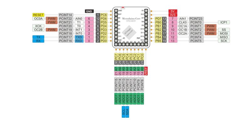
* Microduino standard interface (UPin-27) | * Microduino standard interface (UPin-27) | ||
[[file:Micromodule-1x3.jpg|800px|left]] | [[file:Micromodule-1x3.jpg|800px|left]] | ||
| Line 429: | Line 240: | ||
[[file:UPin27.jpg|800px|left]] | [[file:UPin27.jpg|800px|left]] | ||
<br style="clear: left"/> | <br style="clear: left"/> | ||
| − | * Microduino | + | |
| + | * Microduino Upin27 Compatible Modules Pin, occupation planning table | ||
|- | |- | ||
| | | | ||
| Line 442: | Line 254: | ||
| Core+ || RX0 || TX0 || RX1 || TX1 || || || || || || || || || || || || || || || || || || || IN || || | | Core+ || RX0 || TX0 || RX1 || TX1 || || || || || || || || || || || || || || || || || || || IN || || | ||
|- | |- | ||
| − | | | + | | USBTTL|| TX0 || RX0 || || || || || || || || || || || || || || || || || || || || || OUT || OUT || |
|- | |- | ||
| ENC28J60 || || || || IRQ || || || || || CS || || || SO || SI || SCK || || || || || || || || || || IN || | | ENC28J60 || || || || IRQ || || || || || CS || || || SO || SI || SCK || || || || || || || || || || IN || | ||
|- | |- | ||
| − | | | + | | nRF24 || || || INT || || || || || || || CSN || CE || SO || SI || SCK || || || || || || || || || || IN || |
|- | |- | ||
| − | | | + | | WiFi|| || || IRQ || || || || || || || EN || CS || DI || DO || SCK || || || || || || || || || || IN || |
|- | |- | ||
| − | | BT || TX || RX || | + | | BT || (TX) || (RX) ||TX||RX||(TXS)||(RXS)|| || || || |||| || || || || || || || || || || || || IN || |
|- | |- | ||
| − | | | + | | GPS || TX || RX ||(TX)||(RX)|| || || || || || || || || || || || || || || || || || || || IN || |
|- | |- | ||
| SD || || || || || || || || CS || || || || D0 || DI || SCK || CD || || || || || || || || || IN || | | SD || || || || || || || || CS || || || || D0 || DI || SCK || CD || || || || || || || || || IN || | ||
| Line 460: | Line 272: | ||
| 10DOF || || || || || || || || || || || || || || || || || || || SDA || SCL || || || || IN || | | 10DOF || || || || || || || || || || || || || || || || || || || SDA || SCL || || || || IN || | ||
|- | |- | ||
| − | | | + | | Amplifier || || || || || || || || || || L || R || || || || || || || || || || || || || IN || |
|- | |- | ||
| BM || || || || || || || || || || || || || || || || || || || || || || || OUT/IN || OUT || | | BM || || || || || || || || || || || || || || || || || || || || || || || OUT/IN || OUT || | ||
| Line 467: | Line 279: | ||
|- | |- | ||
| NFC || || || || || || || || || || || || || || || || || || || SDA || SCL || || || || IN || | | NFC || || || || || || || || || || || || || || || || || || || SDA || SCL || || || || IN || | ||
| + | |- | ||
| + | | Zigbee ||TX0 ||RX0 ||TX1 ||RX1 ||TXS ||RXS|| || || || || || || || || || || || || || || || || || IN || | ||
| + | |- | ||
| + | | Coreble || || || || || || || || || || || || || || || || || || || || || || || || IN || | ||
| + | |- | ||
| + | | TFT || || || || || || || || || || || || || || || || || || || || || || || || IN || | ||
|} | |} | ||
|} | |} | ||
| + | |||
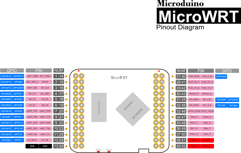
| + | ==Microduino Hpin52 Pinout Summary== | ||
| + | |||
| + | [[file:MicroWRT Image1.png|800px|thumb|left]] | ||
| + | <br style="clear: left"/> | ||
| − | |||
| − | |||
| − | |||
{| class="wikitable" style="width:800px;border:2px solid #000000; -moz-border-radius:5px 5px 5px 5px; -webkit-border-radius:5px 5px 5px 5px;" cellspacing=0 cellpadding=0 | {| class="wikitable" style="width:800px;border:2px solid #000000; -moz-border-radius:5px 5px 5px 5px; -webkit-border-radius:5px 5px 5px 5px;" cellspacing=0 cellpadding=0 | ||
| | | | ||
This Wiki was built in '''2013/June/11''', there are '''[[Special:SpecialPages|{{NUMBEROFARTICLES}} pages]]''', '''[[Special:NewFiles|{{NUMBEROFFILES}} files uploaded]]''' and '''[[Special:Statistics|{{NUMBEROFEDITS}} revises]]'''. <br>To learn more information, please visit '''[[Special:RecentChanges|Recent Changes]]'''. | This Wiki was built in '''2013/June/11''', there are '''[[Special:SpecialPages|{{NUMBEROFARTICLES}} pages]]''', '''[[Special:NewFiles|{{NUMBEROFFILES}} files uploaded]]''' and '''[[Special:Statistics|{{NUMBEROFEDITS}} revises]]'''. <br>To learn more information, please visit '''[[Special:RecentChanges|Recent Changes]]'''. | ||
| − | |||
|} | |} | ||
Revision as of 06:34, 24 October 2014
| Language: | English • 中文 |
|---|
| Welcome to Microduino Wiki
| |||||||
|---|---|---|---|---|---|---|---|
|
| |||||||
|
| Homepage: http://www.Microduino.cc/ |
| Facebook: https://www.Facebook.com/Microduino/ |
| Twitter: http://www.Twitter.com/Microduino/ |
|
Fritzing :File:Microduino-Fritzing.zip Downlaod Microduino IDE package:【Arduino IDE Microduino Configuration】 |
Microduino Hpin52 Series | |
|
|
|
|
Microduino HPin88 Series | |
|
|
|
|
|
|
Microduino Game machine&Controller series | |
Microduino Aircraft series | |
Microduino Robot Series | |
Microduino Player Community ProjectMicroduino Player Community Project
Microduino Upin27 Pinout Summary | |||||||||||||||||||||||||||||||||||||||||||||||||||||||||||||||||||||||||||||||||||||||||||||||||||||||||||||||||||||||||||||||||||||||||||||||||||||||||||||||||||||||||||||||||||||||||||||||||||||||||||||||||||||||||||||||||||||||||||||||||||||||||||||||||||||||||||||||||||||||||||||||||||||||||||||||||||||||||||||||||||||||||||||||||||||||||||||||||||||||||||||||||||||||||||||||||||||||||||||||||||||||||||||||||||||||||||||||||||||||||||||||||||||||||||||||||||||||||||||||||||||||||||||||||||||||||||||||||||||||
| |||||||||||||||||||||||||||||||||||||||||||||||||||||||||||||||||||||||||||||||||||||||||||||||||||||||||||||||||||||||||||||||||||||||||||||||||||||||||||||||||||||||||||||||||||||||||||||||||||||||||||||||||||||||||||||||||||||||||||||||||||||||||||||||||||||||||||||||||||||||||||||||||||||||||||||||||||||||||||||||||||||||||||||||||||||||||||||||||||||||||||||||||||||||||||||||||||||||||||||||||||||||||||||||||||||||||||||||||||||||||||||||||||||||||||||||||||||||||||||||||||||||||||||||||||||||||||||||||||||||
| |||||||||||||||||||||||||||||||||||||||||||||||||||||||||||||||||||||||||||||||||||||||||||||||||||||||||||||||||||||||||||||||||||||||||||||||||||||||||||||||||||||||||||||||||||||||||||||||||||||||||||||||||||||||||||||||||||||||||||||||||||||||||||||||||||||||||||||||||||||||||||||||||||||||||||||||||||||||||||||||||||||||||||||||||||||||||||||||||||||||||||||||||||||||||||||||||||||||||||||||||||||||||||||||||||||||||||||||||||||||||||||||||||||||||||||||||||||||||||||||||||||||||||||||||||||||||||||||||||||||
Microduino Hpin52 Pinout Summary
|
This Wiki was built in 2013/June/11, there are 53 pages, 4,742 files uploaded and 19,107 revises. |
