Reflex Battle

From Microduino Wiki
Revision as of 10:35, 15 September 2017 by Fengfeng (talk | contribs) (Created page with " {| style="width: 1000px;" |- | ==Overview== 600px|center Ever wonder whether you or your friend Bob has faster reflexes? Make this project and fi...")
(diff) ← Older revision | Latest revision (diff) | Newer revision → (diff)
Jump to: navigation, search

Overview

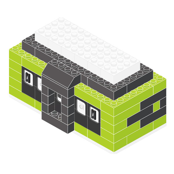
Reflex Battle.jpg

Ever wonder whether you or your friend Bob has faster reflexes? Make this project and find out. Challenge your friends, parents, teachers...or even your dog. It'll be the showdown of the century!


Modules List

Module

Module Quantity Function
Core 1 Core
mBattery 1 Program download and power supply
Hub 1 Sensor adapter
Crash 2 Switch
Color KED 2 Color LED
Buzzer 1 Produce sound

Other Equipment

  • USB Cable*1
  • Sensor Cable*5
  • Sensor shell*5
  • Building blocks or other fixation structures

Modules Setup

Reflex Battle Connection.png
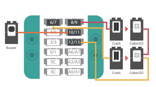
 We recommend you use the same Sensor Cable colors in the diagram. 
  • Assemble modules and sensors together:
    • Stack Core and Hub onto mBattery;
    • Connect the two Crash buttons to pin 6/7 and 8/9 on Hub;
    • Connect Buzzer to pin 10/11 on Hub;
    • Connect two Color LEDs in serial and then connect them to pin 12/13 of Hub;
    • Insert one end of USB Cable into mBattery and then connect the other to computer.

Program Download

See Software Setup: Arduino


Technical Specifications

  • Serial number of Crash: MSDS11
  • Digital sensor
  • For details, see Sensor-Crash

Q&A