|
The guide below is a software setup guide for Mac OS aimed for general use of Microduino products.
For kit specific getting started guides please follow the appropriate links in the #Kit_Specific_Software_Setup_Guides section:
Kit Specific Software Setup Guides
If your kit is not listed, please proceed following the general setup guide below.
Download
Download the latest MacOS IDE (Version 6.0, 2020-02-27): HERE
Download the latest MacOS IDE (Version 5.0, 2019-03-25): HERE
Installation
Security Settings
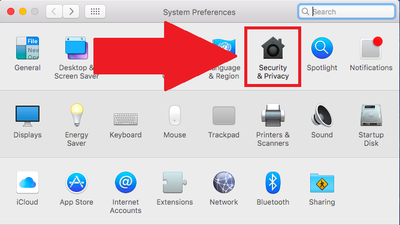
- Change your settings to allow identified developers by going to: (Apple Logo) >>> System Preferences...
- Then go to Security & Privacy.
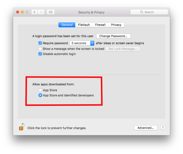
- Click on then Lock icon and enter your credentials to be able to change settings.
- Under Allow apps download from: select App Store and identified developers
- Click the Lock icon again to lock and save changes.
Drivers Installation
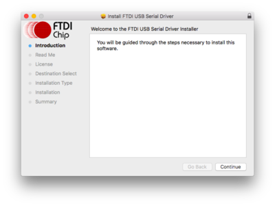
FTDI Driver
- Open the downloaded file. A folder will open containing the Microduino IDE and drivers for the hardware.
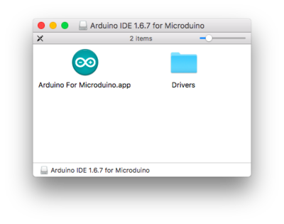
- Open the Drivers folder. Drivers are needed to communicate with the Microduino hardware.
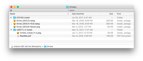
- Install ONE of the driver packages:
- Driver_OS10.3.mpkg if you have Mac OS 10.3 or below.
- Driver_OS10.4-10.8.mpkg if you have Mac OS 10.4 to Mac OS 10.8.
- Driver_OS10.9-Newer.mpkg if you have Mac OS 10.9 or newer.
- Follow the on-screen instructions to install the driver.
CP210X Driver
- Once completed return to the Drivers folder. Open the CP210X Install folder. This is another driver that needs to be installed.

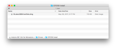
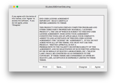
- Open SliLabsUSBDriverDisk.dmg. Follow the on-screen instructions to install the driver.
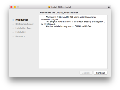
CH34x Driver
- Once completed return to the Drivers folder. Open the USBTTL-C Install folder. This is another driver that needs to be installed.
- Important Note: This driver requires you to restart your computer. Save all work before installing this driver!!!
- (Note: The Mac OS X 10.6 or older package does not contain this. Therefore, you can skip this step.)
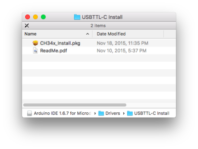
- Open CH34x_Install.pkg. Follow the on-screen instructions to install the driver.
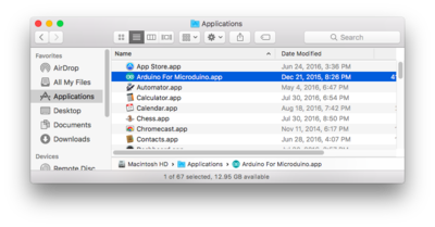
Application Copying
- Drag the Arduino for Microduino.app application to your Applications folder to install the IDE.
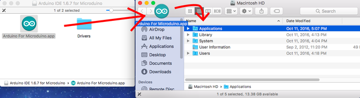 ] ]
- The software is now installed and ready to use. Double-click the application to launch it!
Microduino / mCookie CoreUSB Setup
[Expand]
For Microduino CoreUSB or mCookie CoreUSB ONLY. Expand to view contents.
Otherwise, skip to the next section.
- Your Mac is trying to recognize the new device. Briefly press the key to the right of your shift key.
- A popup will appear saying that your keyboard cannot be recognized. Click "Skip".
- Select the keyboard layout for your region (ANSI for most users). Click done.
Confirm Drivers Installed Successfully
Confirm that the drivers are installed successfully based on your hardware.
Refer to the table below for which programmer each kit uses:
| Programmer
|
Contained in Kit
|
Programmable Boards
|
| USBTTL
|
102 Basic Kit
|
Core, Core+, CoreRF
|
| mBattery
|
Itty Bitty City, 202 Advanced Kit, 302 Expert Kit
|
Core, Core+, CoreRF
|
| (CoreUSB)*
|
X01 Series Kits: 101 Basic Kit; 201 Advanced Kit; 301 Expert Kit
|
CoreUSB
|
- NOTE: CoreUSB is a core module with an integrated programmer.
USBTTL
- Connect Microduino-USBTTL to your computer. Verify that there are available Port options under Tools.
CoreUSB
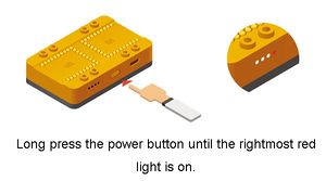
mBattery
IMPORTANT: Ensure that mBattery is "ON" by pressing and holding the button. A red LED should be on, which indicates that power is being supplied to the modules.
- Verify that there are available Port options under Tools.
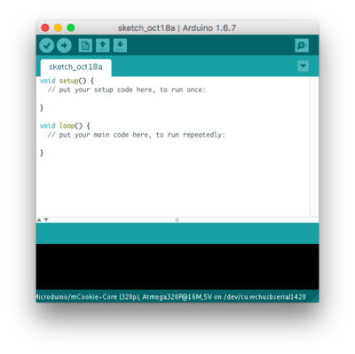
Selecting Board Type and Processor
Selecting the Board Type and Processor is required to compile the correct code for the core module.
Configuring the software is done under Tools > Board and Tools > Processor.
Below is the table which lists all the core modules with corresponding Board and Processor. The table also lists kits that contain specific core modules.
Example usage would be for the Core module in Itty Bitty City. Board is Microduino/mCookie-Core (328p) and Processor is Atmega328P@16M,5V.
| Name
|
Board
|
Processor
|
Contained in Kit
|
| Core (168pa)
|
Microduino/mCookie-Core (168pa)
|
Atmega168pa@8M,3.3V
|
| Atmega168pa@16M,5V
|
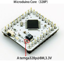
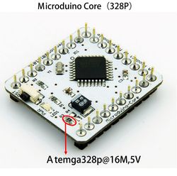
| Core (328p)
|
Microduino/mCookie-Core (328p)
|
Atmega328P@8M,3.3V
|
| Atmega328P@16M,5V
|
Itty Bitty City Kit, X02 Series Kits: 102 Basic Kit; 202 Advanced Kit; 302 Expert Kit
|
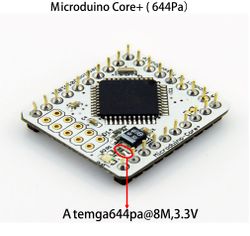
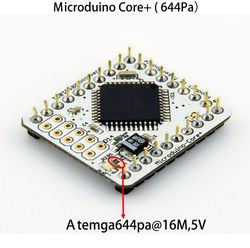
| Core+ (644pa)
|
Microduino/mCookie-Core+ (644pa)
|
Atmega644pa@16M,3.3V
|
| Atmega644pa@16M,5V
|
302 Expert Kit
|
| Core+ (1284pa)
|
Microduino/mCookie-Core+ (1284pa)
|
Atmega1284pa@8M,3.3V
|
| Atmega1284pa@16M,5V
|
| CoreUSB
|
Microduino/mCookie-Core USB (32u4)
|
USB
|
X01 Series Kits: 101 Basic Kit; 201 Advanced Kit; 301 Expert Kit
|
| CoreRF
|
Microduino/mCookie RF (128rfa1)
|
Determining Processor Variant
Core
Core+
Arduino IDE Basics
Interface
- [Verify]: Checks for errors in the code.
- [Upload]: Uploads the program to a MCU.
- [Serial Monitor]: Useful in debugging programs.
Tools
- [Board]: Select the corresponding core module to which the program is being uploaded.
- [Processor]: Select the corresponding processor.
- [Port]: Select the common USB port.
Uploading Code
- Select board type and processor.
- Select the port.
- Click upload.
- Note: If using mBattery to upload to a core module. Ensure that mBattery is "ON" and supplying power to the modules. There will be a red LED on.
|


