Difference between revisions of "Rhythm Lamp"
From Microduino Wiki
(Wrong Pin. Should be D6 instead of A6) |
(Corrected PIN number) |
||
| Line 87: | Line 87: | ||
==Hardware Buildup== | ==Hardware Buildup== | ||
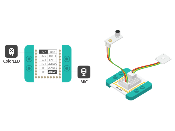
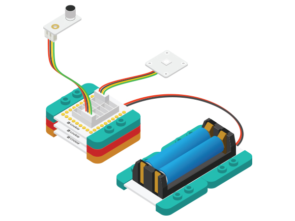
| − | *Setup 1:Connect MIC to A0 pin of Sensorhub and Colored LED to | + | *Setup 1:Connect MIC to A0 pin of Sensorhub and Colored LED to PIN 6. Both sides of Sensorhub have pin description, which can be connected with sensors accordingly. |
[[File:CoreUSB_mic_steup1.jpg|600px|center]] | [[File:CoreUSB_mic_steup1.jpg|600px|center]] | ||
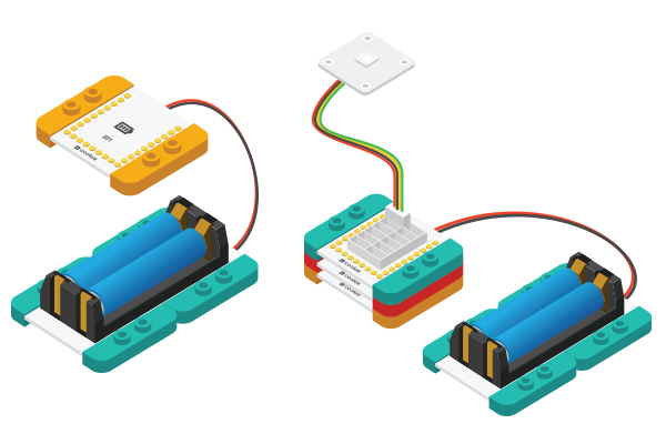
*Setup 2:Connect the activated battery box to BM. | *Setup 2:Connect the activated battery box to BM. | ||
Revision as of 19:26, 27 July 2016
| Language: | English • 中文 |
|---|
ContentsObjectiveSpeak toward MIC, the lamp will change along with the sound rhythm. principle
MIC sensor can turn sound signal to electricity signal. It can detect sound volume but can't detect certain sound.
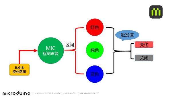
Detect sound volume via MIC sensor and the system will judge which color range the sound belongs to. At the same, comparing with the pre-set trigger value and choosing to open or close light change, therefore, to control color change of the lamp. Equipment
Preparation
Program Description
  int v=analogRead(A0);
  Serial.println(v);
  if(millis()-timer[0]>100)
  {
    timer[0]=millis();
    if(v>zone_vol[0])
      zone=0;//Red
    else if(v>zone_vol[1])
      zone=1;//Green
    else if(v>zone_vol[2])
      zone=2;//Blue
    else
      zone=9;
  }
  switch(zone)
  {
  case 0:
    if(color!=0)
      vol[0]=map(v,0,1023,0,255);//Red
    else
      vol[0]=10;
    break;
  case 1:
    if(color!=1)
      vol[1]=map(v,0,1023,0,255);//Green
    else
      vol[1]=10;
    break;
  case 2:
    if(color!=2)
      vol[2]=map(v,0,1023,0,255);//Blue
    else
      vol[2]=10;
    break;
  }
  // Some example procedures showing how to display to the pixels:
  colorWipe(strip.Color(vol[0],vol[1], vol[2]), 20);
Hardware Buildup
ResultSpeak towards MIC and you'll find different effect. Video |
