Difference between revisions of "Microduino-Shield UNO"
From Microduino Wiki
| Line 3: | Line 3: | ||
| | | | ||
[[file:Microduino-Uno-ks.jpg|400px|thumb|right|Microduino-Uno]] | [[file:Microduino-Uno-ks.jpg|400px|thumb|right|Microduino-Uno]] | ||
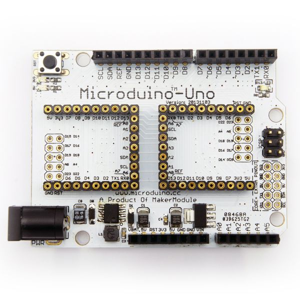
| + | Microduino-Uno is an extension board based on official Arduino board, you can use it just like a Arduino with Microduino FT232R and Microduino Core module. | ||
|- | |- | ||
| | | | ||
| − | == | + | ==Features== |
| − | * | + | *Pin compatible with Arduino uno; |
| − | * | + | *Support wide voltage DC power input (8 ~ 35V input); |
| − | *2. | + | *2.54 pitch Female Heade is Microduino module based, the same name of the pins are connected to each other in the board, each pin is installed with the power and ground to facilitate debugging; |
| − | * | + | *Define unified interface Microduino specification and contain rich peripheral modules. Set up the quick connection with other Microduino modules and sensors easily and flexibly. |
| + | |||
==Specifications== | ==Specifications== | ||
| − | * | + | *Support wide voltage DC power input (8 ~ 35V input); |
| − | * | + | *5V and 3.3V regulator; |
| − | * | + | *Digit IO port D13 connect the LED light,high lights; |
| − | * | + | *Reset button on board; |
| − | * | + | * Add serial port(RX1,TX1)、I2C(SCL,SDA)、power(5V,3.3V)and ground pin; |
| − | * | + | *ICSP pin on board; |
| − | * | + | *Two Microduino UPIN27 seat interconnect in the board. |
[[File:Uno-Pinout-1.jpg|800px|thumb|center|Microduino-Uno-Pinout]] | [[File:Uno-Pinout-1.jpg|800px|thumb|center|Microduino-Uno-Pinout]] | ||
| Line 24: | Line 26: | ||
[[File:Uno-Pinout-2.jpg|800px|thumb|center|Microduino-Uno-Pinout]] | [[File:Uno-Pinout-2.jpg|800px|thumb|center|Microduino-Uno-Pinout]] | ||
| − | == | + | ==Document== |
Eagle PCB '''[[File:Microduino-UNO.zip]]''' | Eagle PCB '''[[File:Microduino-UNO.zip]]''' | ||
| − | === | + | ===Main component=== |
| − | * | + | *Switching Regulator Chip:LM2674 '''[[File:LM2674.pdf]]''' |
| − | * | + | *LDO regulator chip:ASM1117 '''[[File:AMS1117-3.3.pdf]]''' |
| − | * | + | *Wound Chip Power Inductors:RWPA4018S '''[[File:RWPA4018S.pdf]]''' |
| − | * | + | *Schottky diodes:SOD123 '''[[File:SOD-123.pdf]]''' |
| − | |||
| − | |||
| − | |||
| − | |||
| − | |||
| − | |||
| − | + | ==Development== | |
| + | Set up the quick connection with other Microduino modules and sensors easily and flexibly. | ||
| − | + | ==Application== | |
| + | You can download the program that Microduino provides to test the LED connected to I/O port D13: | ||
| − | + | *Prepared Hardware:Microduino FT232R、Microduino Core、Microduino UNO; | |
| + | *Prepared Software:Microduino provides testing program(Arduino part)、Arduino IDE(1.0 release and upper); | ||
| + | *Open Arduino IDE's Blink test program, card type choose "Microduino Core (Atmega328P@16M,5V)",download directly. After finished download,you can see the onboard LED flashes every second once; | ||
==Pictures== | ==Pictures== | ||
Revision as of 05:34, 7 February 2014
|
Microduino-Uno is an extension board based on official Arduino board, you can use it just like a Arduino with Microduino FT232R and Microduino Core module. |
ContentsFeatures
Specifications
DocumentEagle PCB File:Microduino-UNO.zip Main component
DevelopmentSet up the quick connection with other Microduino modules and sensors easily and flexibly. ApplicationYou can download the program that Microduino provides to test the LED connected to I/O port D13:
Pictures |


