Difference between revisions of "MCookie-Motor"
From Microduino Wiki
(Created page with "{{Language|mCookie-Motor}} {| style="width: 800px;" |- | 400px|thumb|right|mCookie-Motor mCookie-Motor is a DC motor controller with PWM(Pulse W...") |
|||
| (8 intermediate revisions by 5 users not shown) | |||
| Line 5: | Line 5: | ||
[[File:motor-motor-rect.jpg|400px|thumb|right|mCookie-Motor]] | [[File:motor-motor-rect.jpg|400px|thumb|right|mCookie-Motor]] | ||
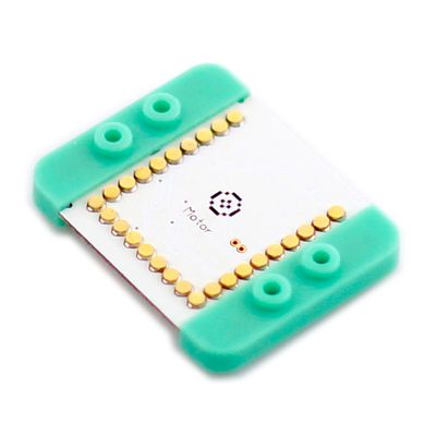
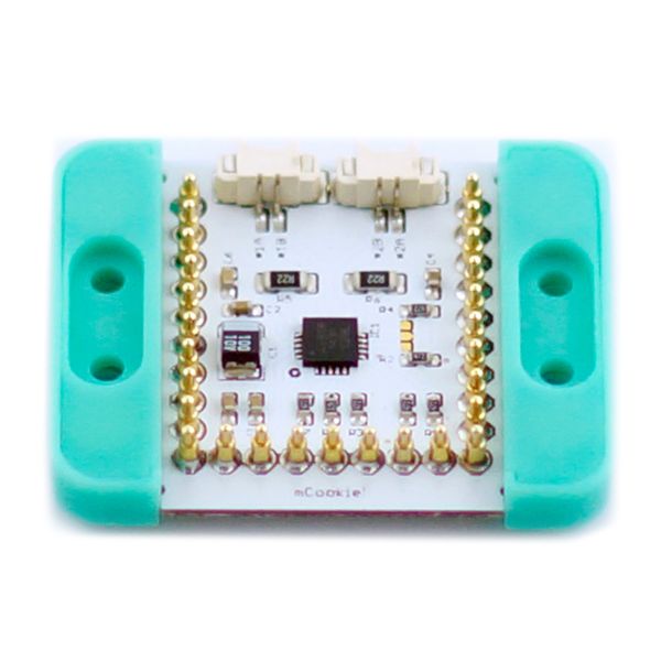
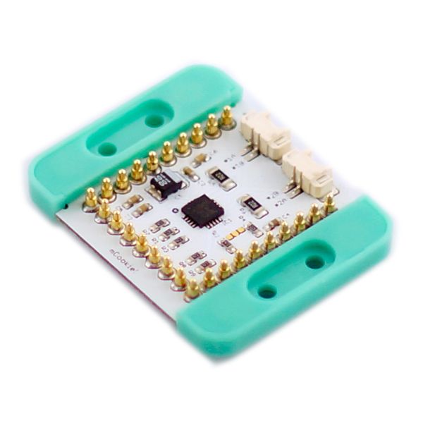
| − | mCookie-Motor is a DC motor controller with PWM(Pulse Width Modulation). The speed of the motor can be controlled through PWM and | + | mCookie-Motor is a DC motor controller with PWM (Pulse Width Modulation) for various speed control. The speed of the motor can be controlled through PWM and direction (forward or backwards). This module needs to be powered with a sufficient power supply such as: |
| − | + | *[[MCookie-BM_shield|BM shield]] with a [[MCookie-BM|BM module]] | |
| + | *[[MCookie-Battery|mBattery]]. | ||
==Features== | ==Features== | ||
| − | *Current & speed limited by internal PWM | + | *Current & speed limited by internal PWM; |
| − | *Synchronous | + | *Synchronous double-channel can reduce power consumption; |
*DC motor braking mode; | *DC motor braking mode; | ||
| − | *Capable of controlling two DC motors | + | *Capable of controlling two DC motors. |
| + | *Speed and direction control. | ||
| + | *Uses standard connectors: 2 pin, 1.25mm pitch JST connectors. | ||
==Specification== | ==Specification== | ||
| Line 34: | Line 37: | ||
| GND||GND||Ground | | GND||GND||Ground | ||
|} | |} | ||
| − | '''Note: The pins including 5, 6, 7 and 8 cannot be occupied by other sensors while using the Motor or it may cause problems. | + | '''Note: |
| − | + | *The pins including 5, 6, 7 and 8 cannot be occupied by other sensors while using the Motor or it may cause problems. | |
| + | *Cannot be power without sufficient power supply such as through only CoreUSB. Module Motor must be powered on by: | ||
| + | **[[MCookie-BM_shield|BM shield]] with a [[MCookie-BM|BM module]] | ||
| + | **[[MCookie-Battery|mBattery]]. | ||
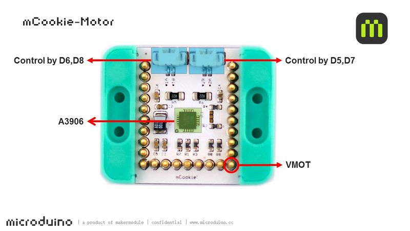
[[File:motor-Pinout-1Big.jpg|800px|thumb|center]] | [[File:motor-Pinout-1Big.jpg|800px|thumb|center]] | ||
| − | |||
==Document== | ==Document== | ||
Latest revision as of 22:21, 29 March 2017
| Language: | English • 中文 |
|---|
|
mCookie-Motor is a DC motor controller with PWM (Pulse Width Modulation) for various speed control. The speed of the motor can be controlled through PWM and direction (forward or backwards). This module needs to be powered with a sufficient power supply such as:
ContentsFeatures
Specification
Note:
DocumentDevelopmentDC Motor Wire Connection
//(D6, D8) controls motor (1A, 1B)
#define OUT1A 6
#define OUT1B 8
//(D5, D7) controls motor (2A, 2B)
#define OUT2A 5
#define OUT2B 7
PWM Rate ControlProject
#define OUT1A 6
#define OUT1B 8
#define OUT2A 5
#define OUT2B 7

void setup()
{
  pinMode(OUT1A, OUTPUT);
  pinMode(OUT1B, OUTPUT);
  pinMode(OUT2A, OUTPUT);
  pinMode(OUT2B, OUTPUT);
}

void loop()
{
head();
delay(2000);
back();
delay(1000);
stop();
delay(500);
}

void head()
{
  digitalWrite(OUT1A, HIGH);
  digitalWrite(OUT1B, LOW);
  digitalWrite(OUT2A, HIGH);
  digitalWrite(OUT2B, LOW);
}
void back()
{
  digitalWrite(OUT1A, LOW);
  digitalWrite(OUT1B, HIGH);
  digitalWrite(OUT2A, LOW);
  digitalWrite(OUT2B, HIGH);
}
void stop()
{
  digitalWrite(OUT1A, LOW);
  digitalWrite(OUT1B, LOW);
  digitalWrite(OUT2A, LOW);
  digitalWrite(OUT2B, LOW);
}
//(D6, D8) controls motor (1A, 1B)
#define OUT1A 6
#define OUT1B 8
//(D5, D7) controls motor (2A, 2B)
#define OUT2A 5
#define OUT2B 7

void setup()
{
  pinMode(OUT1A, OUTPUT);
  pinMode(OUT1B, OUTPUT);
  pinMode(OUT2A, OUTPUT);
  pinMode(OUT2B, OUTPUT);
}

void loop()
{
  for (int fadeValue = 0; fadeValue <= 255; fadeValue += 5)
    //Loop statement. Along with PWM rate increases, you can change brightness level by controlling fadeValue.
  {
    analogWrite(OUT1A, fadeValue);  //Write rate level into the motor
    digitalWrite(OUT1B, LOW);
    analogWrite(OUT2A, fadeValue);
    digitalWrite(OUT2B, LOW);
    delay(100);                       //Delay time of rate. (The unit is ms)
  }
  for (int fadeValue = 255; fadeValue >= 0; fadeValue -= 5)
    // Loop statement. Along with PWM rate decreases, you can change brightness level by controlling fadeValue.
  {
    digitalWrite(OUT1A, LOW);
    analogWrite(OUT1B, fadeValue);  // Write rate level into the motor
    digitalWrite(OUT2A, LOW);
    analogWrite(OUT2B, fadeValue);
    delay(100);                     // Delay time of rate. (The unit is ms)
  }
  delay(1000);
}
Other Projects: PurchaseHistoryPicturesVideo |


