Difference between revisions of "MWatch"
From Microduino Wiki
(Created page with "{{Language| mWatch }} {| style="width: 800px;" |- | ==Objective== Use mCookie to build a simple watch. 400px|center ==Principle== Acquire time via RTC...") |
(→Principle) |
||
| (4 intermediate revisions by the same user not shown) | |||
| Line 9: | Line 9: | ||
==Principle== | ==Principle== | ||
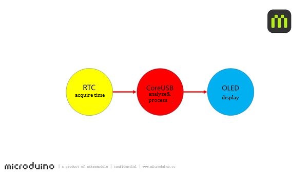
Acquire time via RTC module and display time on the OLED screen. | Acquire time via RTC module and display time on the OLED screen. | ||
| − | [[File: | + | [[File: 1mWatch-sch.jpg|600px|center]] |
==Equipment== | ==Equipment== | ||
| Line 63: | Line 63: | ||
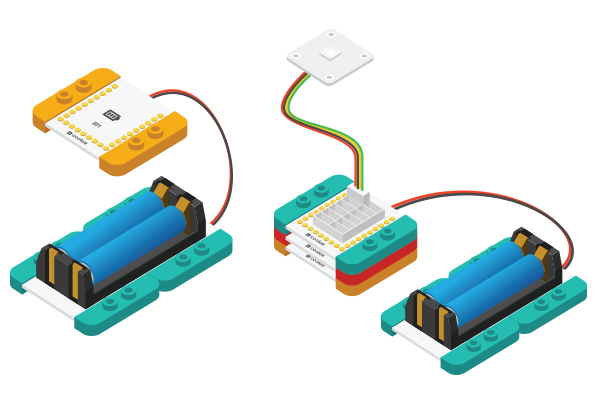
*Setup 1:Connect the activated battery box and BM module. | *Setup 1:Connect the activated battery box and BM module. | ||
[[File:CoreUSB_Ble_steup2.jpg|600px|center]] | [[File:CoreUSB_Ble_steup2.jpg|600px|center]] | ||
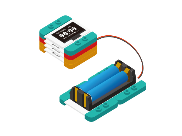
| − | *Setup 2:Stack all modules together | + | *Setup 2:Stack all modules together without fixed order and finish circuit buildup. |
[[File:mWatch_steup3.jpg|600px|center]] | [[File:mWatch_steup3.jpg|600px|center]] | ||
Latest revision as of 03:51, 28 January 2016
| Language: | English • 中文 |
|---|
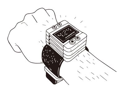
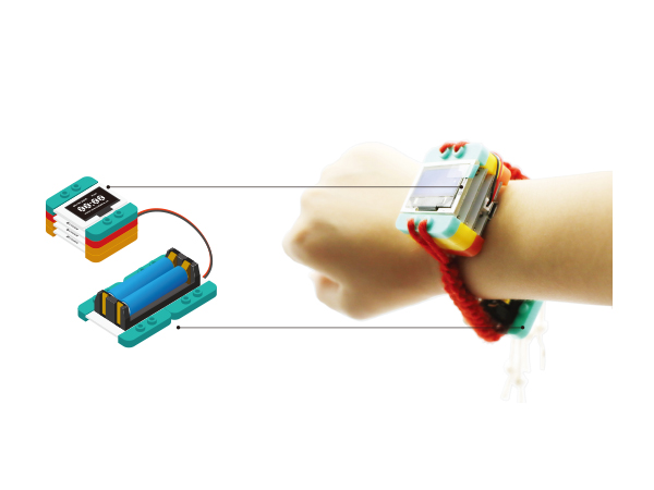
ContentsObjectiveUse mCookie to build a simple watch. PrincipleAcquire time via RTC module and display time on the OLED screen. Equipment
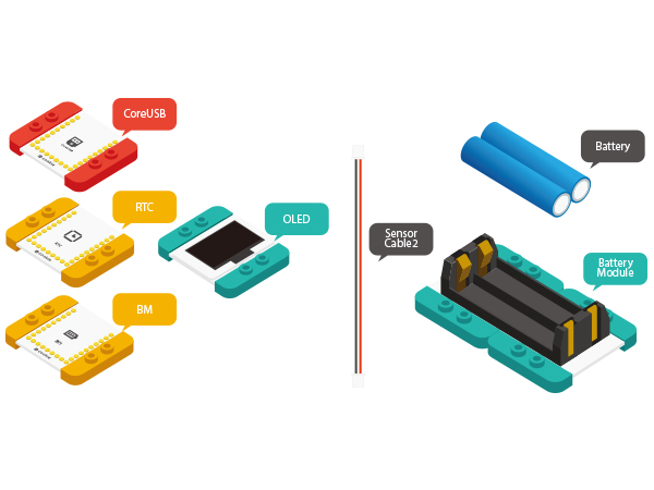
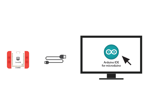
Preparation
Program Description
void setRtcTime (byte _year, byte _month, byte _day, byte _week, byte _hour, byte _minute, byte _sec)
{
  //clear out all the registers
  rtc.initClock();
  rtc.setDate(_day, _week, _month, 0, _year);
  rtc.setTime(_hour, _minute, _sec);
}
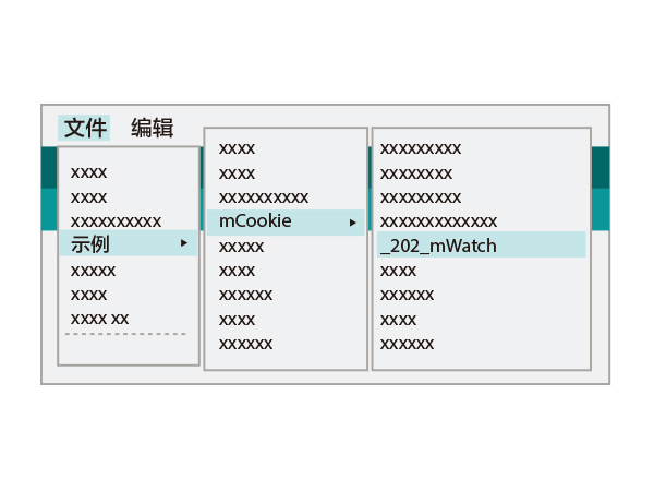
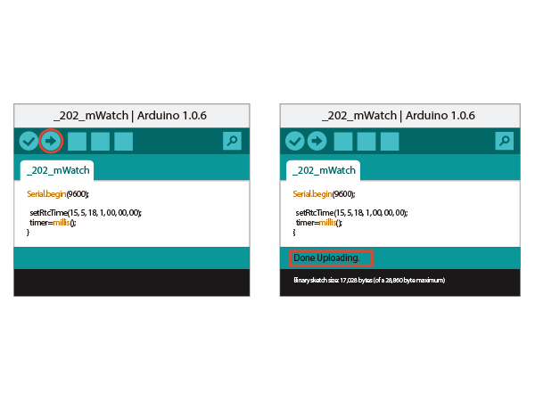
Code DebuggingFind this code section and set the initial time of the RTC module. Re-load the code to CoreUSB after setting. setRtcTime(15, 5, 18, 1, 00, 00, 00);Enter "//" before this code section after loading the program, the whole section will turn gray and then re-load the program and you'll see RTC can time automatically. ("//" means "comment out the program code and do not perform ". In this way, you needn't run the program after calibration or the system will need re-set time after power-fail and re-start. ) //setRtcTime(15, 5, 18, 1, 00, 00, 00);Hardware Buildup
ResultThe first line shows data and week. The second line displays: time and the third displays custom text. Video |
