Difference between revisions of "Microduino NFC Unlocks Computer"
| Line 4: | Line 4: | ||
| | | | ||
==Outline== | ==Outline== | ||
| − | * | + | *Project: Microduino NFC Unlocks Computer |
| − | * | + | *Objective: Enter the password is very complicated in some time, so this tutorial will resolve this problem. Microduino use the NFC module and nRF24 wireless module to unlock the computer immediately via an electronic tags. If you want to control multiple computers, only need one Microduino NRF to control multiple electronic tags. |
| − | * | + | *Difficulty: High |
| − | *Time- | + | *Time-consuming: 6 hours |
| − | * | + | *Maker: Microduino Studio-YLB |
==Principle== | ==Principle== | ||
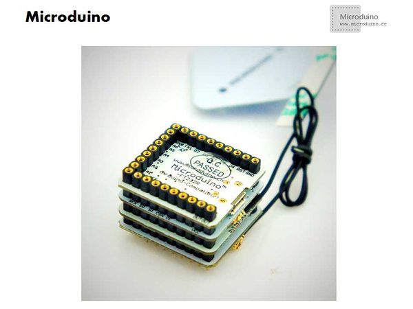
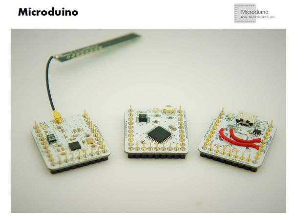
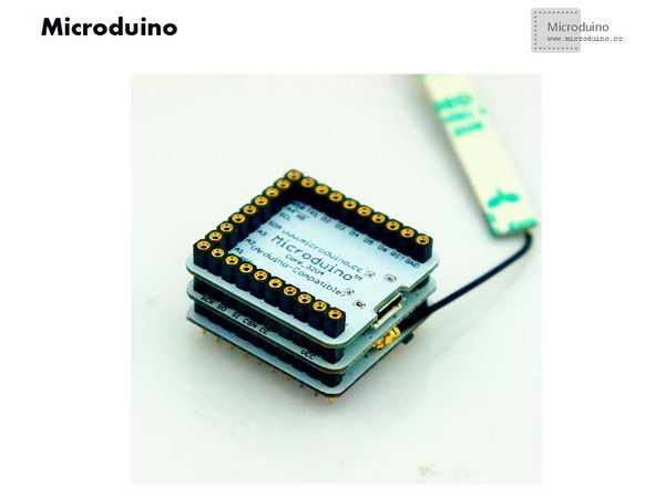
| − | This system uses Microduino nRF24 module to set up network. The master system use the | + | This system uses Microduino nRF24 module to set up network. The master system use the Microduino core module (Microduino-Core or Microduino Core+ or Microduino 32U4), Microduino nRF24, Microduino NFC, Microduino FT232R which build a gateway. |
| − | Using the Miccroduino-Core, Microduino nRF24 and AVR-USB-HID made by yourself to build a network point. Every | + | Using the Miccroduino-Core, Microduino nRF24 and AVR-USB-HID made by yourself to build a network point. Every electronic tag has different ID, the gateway identifies different ID, then sends the command to it, otherwise waiting for electronic tag. After the network point received the command, trigger the AVR-USE-HID device to input the passward (actually simulate the keyboard to input the keyboard value), then unlock the computer immediately. |
[[File:Microduino_nfc—nrf.jpg||600px|center|thumb]] | [[File:Microduino_nfc—nrf.jpg||600px|center|thumb]] | ||
| Line 39: | Line 39: | ||
|Microduino-Core||1||Core | |Microduino-Core||1||Core | ||
|- | |- | ||
| − | |Microduino-FT232R ||1|| | + | |Microduino-FT232R ||1||Download program |
|- | |- | ||
|Microduino-nRF24 ||1||Wireless | |Microduino-nRF24 ||1||Wireless | ||
| Line 57: | Line 57: | ||
Download UsbKeyboard library:https://github.com/suapapa/arduino_library_UsbKeyboard | Download UsbKeyboard library:https://github.com/suapapa/arduino_library_UsbKeyboard | ||
| − | Download RF24 | + | Download RF24 library: https://github.com/maniacbug/RF24/ |
| − | Download NFC | + | Download NFC library: https://github.com/adafruit/Adafruit_NFCShield_I2C |
| − | Download test | + | Download test program: https://github.com/Microduino/Microduino_Tutorials/tree/master/Microduino_Advanced_Tutorial/Microduino_nrf_NFC |
==Debug== | ==Debug== | ||
| − | *Step | + | *Step 1: Make AVR-USB-HID device |
| − | The voltage of AVR-USB-HID device must be in 2.8v to 3.6V. We will introduce one method which changed the Microduino power supply to 3.3v. You can change the power | + | The voltage of AVR-USB-HID device must be in 2.8v to 3.6V. We will introduce one method which changed the Microduino power supply to 3.3v. You can change the power selection resistor 0 to 3.3v pin, then the voltage will match the requirement. If you don't want to change the Microduino, there is another method which uses an external Voltage regulator tube, detailed information, please refer to following link: |
http://www.microduino.cc/wiki/index.php?title=Lesson_5--Microduino_Simulates_Computer_Keyboard | http://www.microduino.cc/wiki/index.php?title=Lesson_5--Microduino_Simulates_Computer_Keyboard | ||
**Equipment | **Equipment | ||
| Line 81: | Line 81: | ||
[[File:Microduino_nfc_nrf1.jpg||600px|center|thumb]] | [[File:Microduino_nfc_nrf1.jpg||600px|center|thumb]] | ||
[[File:Microduino_nfc_nrf2.jpg||600px|center|thumb]] | [[File:Microduino_nfc_nrf2.jpg||600px|center|thumb]] | ||
| − | Principle | + | Principle introduction: |
| − | 1.Two 68Ω | + | 1.Two 68Ω resistor play a current-limiting resistance and protection function, to prevent accidental damage the computer USB port or microcontroller port. |
| − | 2.The 2.2kΩ pull-up registor use to identify the bus state. If it connects to D+ and +5v, that means it is a high speed USB device, otherwise | + | 2.The 2.2kΩ pull-up registor use to identify the bus state. If it connects to D+ and +5v, that means it is a high speed USB device, otherwise connects to D- and +5v, will be used as slow speed USB device. In this experiment, the keyboard's speed is slow, so it will connect to D-. |
| − | 3.The 3.3V voltage chip use to power the | + | 3.The 3.3V voltage chip use to power the system which leads to the Microduino core's I/O port voltage will be 3.3v, easy to identify the USB device. |
| − | *Step | + | *Step two: Set up gateway |
**Used module | **Used module | ||
[[File:Microduino_nfc_nrf3.jpg||600px|center|thumb]] | [[File:Microduino_nfc_nrf3.jpg||600px|center|thumb]] | ||
| Line 101: | Line 101: | ||
We set up two points, so will define two points in gateway program, uses the "x" to select the point. If the player want to add more points, only need add more cases and the value of "x" in program. | We set up two points, so will define two points in gateway program, uses the "x" to select the point. If the player want to add more points, only need add more cases and the value of "x" in program. | ||
**Change the test program | **Change the test program | ||
| − | ***Open the program "microduino_nrf_nfc_receive" | + | ***Open the program "microduino_nrf_nfc_receive", point 1 will use "const uint16_t this_node = 1;" then x equal to 1, point 1 will use "const uint16_t this_node = 2;", x equal to 2. This will avoid the data conflict. |
| − | ***Change the | + | ***Change the password. Need to change the key value in key function. You can find the key value in file UsbKeyboard.h of library UsbKeyboard. It only contains a part value of keyboard, but it is enough to use. You can change to your password, then compile the program. |
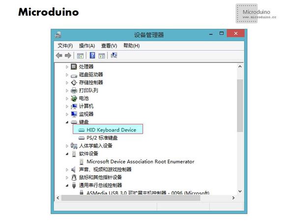
| − | **After | + | **After download, insert the AVR-USB-HID device to computer, if succeeded, you can find the HID Keyboard Device service keyboards of Device Manager. If can't find it, you need to check if there is welding error on AVR-USB-HID. |
[[File:Microduino_nfc_nrf7.jpg||600px|center|thumb]] | [[File:Microduino_nfc_nrf7.jpg||600px|center|thumb]] | ||
*Step 4:Use the notepad to test firstly | *Step 4:Use the notepad to test firstly | ||
| − | Power on the gateway, and point connects to computer by the AVR-USB-HID device, and then use the NRF to identify electronic tag, check the notepad's | + | Power on the gateway, and point connects to computer by the AVR-USB-HID device, and then use the NRF to identify electronic tag, check the notepad's value if match with the password. If yes, then you start to control. |
==Result== | ==Result== | ||
| − | Set up the system, the gateway read the electronic tag 1, then the point 1 will input the | + | Set up the system, the gateway read the electronic tag 1, then the point 1 will input the password automatically to unlock the computer. The same as point 2. |
==Difficulty== | ==Difficulty== | ||
| Line 119: | Line 119: | ||
*Don't confuse the D+, D- when making AVR-USB-HID device; | *Don't confuse the D+, D- when making AVR-USB-HID device; | ||
*Currently Microduino NFC can identify iso14443a type electronic tag; | *Currently Microduino NFC can identify iso14443a type electronic tag; | ||
| − | *Make sure the point and computer are | + | *Make sure the point and computer are matched, otherwise the password is inverse. |
==Video== | ==Video== | ||
|} | |} | ||
Latest revision as of 09:28, 12 September 2016
| Language: | English • 中文 |
|---|
Contents[hide]Outline
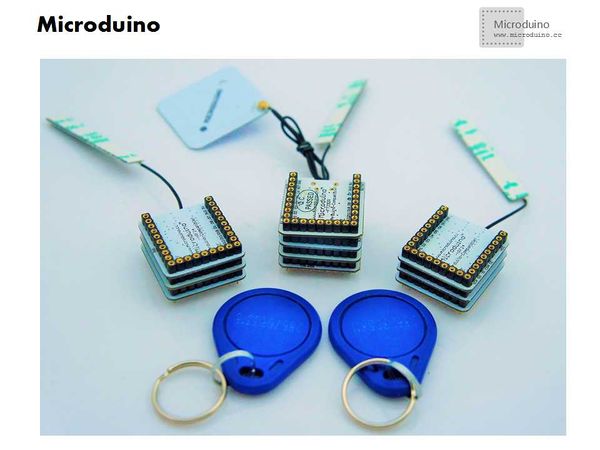
PrincipleThis system uses Microduino nRF24 module to set up network. The master system use the Microduino core module (Microduino-Core or Microduino Core+ or Microduino 32U4), Microduino nRF24, Microduino NFC, Microduino FT232R which build a gateway. Using the Miccroduino-Core, Microduino nRF24 and AVR-USB-HID made by yourself to build a network point. Every electronic tag has different ID, the gateway identifies different ID, then sends the command to it, otherwise waiting for electronic tag. After the network point received the command, trigger the AVR-USE-HID device to input the passward (actually simulate the keyboard to input the keyboard value), then unlock the computer immediately. Bill of MaterialsMicroduino gateway
Microduino network point
Other equipment
DocumentDownload UsbKeyboard library:https://github.com/suapapa/arduino_library_UsbKeyboard Download RF24 library: https://github.com/maniacbug/RF24/ Download NFC library: https://github.com/adafruit/Adafruit_NFCShield_I2C Download test program: https://github.com/Microduino/Microduino_Tutorials/tree/master/Microduino_Advanced_Tutorial/Microduino_nrf_NFC Debug
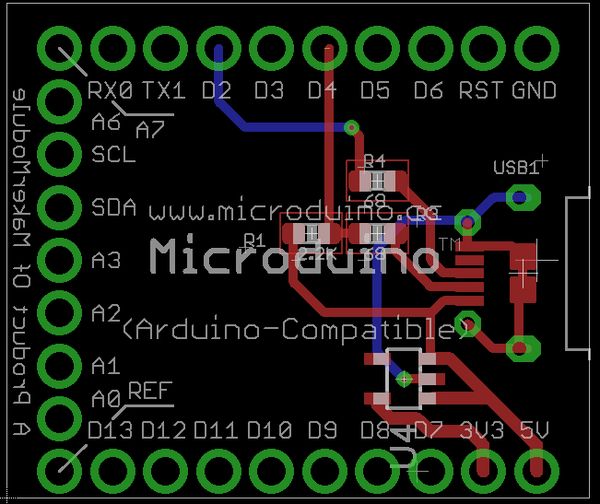
The voltage of AVR-USB-HID device must be in 2.8v to 3.6V. We will introduce one method which changed the Microduino power supply to 3.3v. You can change the power selection resistor 0 to 3.3v pin, then the voltage will match the requirement. If you don't want to change the Microduino, there is another method which uses an external Voltage regulator tube, detailed information, please refer to following link: http://www.microduino.cc/wiki/index.php?title=Lesson_5--Microduino_Simulates_Computer_Keyboard
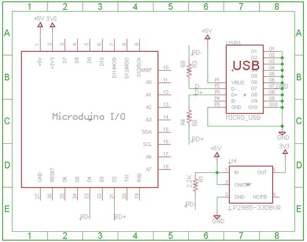
SchematicPrinciple introduction: 1.Two 68Ω resistor play a current-limiting resistance and protection function, to prevent accidental damage the computer USB port or microcontroller port. 2.The 2.2kΩ pull-up registor use to identify the bus state. If it connects to D+ and +5v, that means it is a high speed USB device, otherwise connects to D- and +5v, will be used as slow speed USB device. In this experiment, the keyboard's speed is slow, so it will connect to D-. 3.The 3.3V voltage chip use to power the system which leads to the Microduino core's I/O port voltage will be 3.3v, easy to identify the USB device.
We set up two points, so will define two points in gateway program, uses the "x" to select the point. If the player want to add more points, only need add more cases and the value of "x" in program.
Power on the gateway, and point connects to computer by the AVR-USB-HID device, and then use the NRF to identify electronic tag, check the notepad's value if match with the password. If yes, then you start to control. ResultSet up the system, the gateway read the electronic tag 1, then the point 1 will input the password automatically to unlock the computer. The same as point 2. Difficulty
Pay attention issue
Video |
