Difference between revisions of "Microduino-Shield Stepper"
(Fengfeng moved page Microduino-Shield Stepper to Microduino-Module Stepper) |
(→Specification) |
||
| (6 intermediate revisions by one other user not shown) | |||
| Line 1: | Line 1: | ||
| − | # | + | {{Language|Microduino-Shield Stepper}} |
| + | {| style="width: 800px;" | ||
| + | |- | ||
| + | | | ||
| + | [[File:DSC9332.JPG|400px|thumb|right|Microduino-Shield Stepper]] | ||
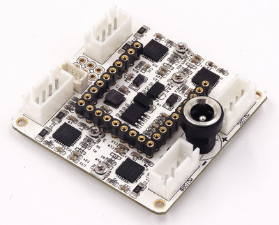
| + | Microduino-Shield Stepper is a DMOS microstep driving plate with a transverter and overcurrent protection, which can drive a two phase stepping motor under the full, half, 1/4, 1/8 and 1/16 stepping mode, and can operate four motors at most at the same time. | ||
| + | |||
| + | |||
| + | ==Features== | ||
| + | Stepping motor is a kind of electromagnetic device which can transform the pulse signal into corresponding angular displacement(or line displacement), and it is a special motor. Motors operate continuously generally, while the stepping motor has positioning and operating two basic states. When there is a pulse inputted, the stepping motor rotates step by step, and it can turn a fixed angle each time to give it a pulse signal. | ||
| + | *Wide power input range | ||
| + | *Suitable for two phase four-wire stepping motor, and driving 4 at most. | ||
| + | *With only simple stepping and direction controlling interfaces, easy to be controlled. | ||
| + | *Five different stepping modes:Full, half, 1/4, 1/8 and 1/16. | ||
| + | *With an adjustable trim pot that can adjust the maximum current output, to obtain higher stepping rate. | ||
| + | *With automatic current attenuation pattern detection/option. | ||
| + | *With overheating shut down, under voltage lock, and crossover-current protection, three functions. | ||
| + | *Upin27 base, can combine with more Microduino modules. | ||
| + | *With a small base, 46.99mm*40.64mm | ||
| + | |||
| + | ==Specification== | ||
| + | *Electric | ||
| + | **5V stable pressure: Adopt ETA1483 step-down scheme, and the range of the operating voltage is 4.5V~18V, the maximum output current is 2A. | ||
| + | **3.3V stable voltage: AMS1117 stable voltage scheme, and the maximum current can reach at 1A. | ||
| + | **Input voltage detection. A7 pin can detect the input power voltage. | ||
| + | *Motor drive | ||
| + | **With 4 A4988SETTR stepping motor drivers, and the driving power is taken from the input power, and the maximum current of each routine can reach at 2A. | ||
| + | **The description of the driver controlling pins | ||
| + | {|class="wikitable" | ||
| + | |- | ||
| + | |Function||A driver||B driver||C driver||D driver | ||
| + | |- | ||
| + | |ENABLE||D4||D4||D4||D4 | ||
| + | |- | ||
| + | |Step||D5||D6||D7||D8 | ||
| + | |- | ||
| + | |dir ||A0||A1||A2||A3 | ||
| + | |} | ||
| + | *A4988SETTR has three ports to set the microstep resolution of the stepping motor, as shown in the following table | ||
| + | {|class="wikitable" | ||
| + | |- | ||
| + | |MS1||MS2||MS3||Setting of the microstep | ||
| + | |- | ||
| + | |Low||Low||Low||Full stepping | ||
| + | |- | ||
| + | |High||Low||Low||Half stepping | ||
| + | |- | ||
| + | |Low||High||Low||1/4 stepping | ||
| + | |- | ||
| + | |High||High||Low||1/8 stepping | ||
| + | |- | ||
| + | |High||High||High||1/16 stepping | ||
| + | |} | ||
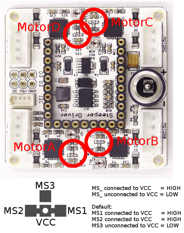
| + | *Stepping motor has a fixed step length generally, such as 1.8°(200 step/turn). A4988 driver can support higher microstep driving way, for example, under the 1/4 mode, the motor will lift the driving resolution of the motor to 800 microsteps per turn through using four different currents, to get a higher control precision. You can get 5 different microstep resolution rates(the default is 1/8 stepping mode) through setting MS1,MS2 and MS3, as shown in the following picture: | ||
| + | [[File:Stepper_Shield_MSx_Select.png||600px|center]] | ||
| + | *You can adjust the maximum output current of the stepping motor through adjusting the potentiometer on the driver. And you can make the stepping motor work on above-fixed voltage to achieve a higher stepping rate. When the stepping motor uses A4988 to drive, the current actually measured of the stepping motor is 70% approximately of the upper limit of the A4988 output current generally, so the current output upper limit needed to be set is the rated current of motor calibration divided by 0.7. You can use the following method to calculate. Work out the corresponding limited current (the current sensing resistor here is 0.05Ω)through measuring the voltage REF pin . | ||
| + | '''Current limitation = VREG X 2.5''' | ||
| + | |||
| + | Therefor, if you want the motor coil to get 1A current, the current limitation should be 1A/0.7 = 1.4A, which is equivalent to VREF = 1.4A/2.5 = 0.56V. You should adjust the VREF voltage to 0.56V through adjusting the potentiometer. | ||
| + | **The metal screw head of the variable resistor is the measuring point of Vref. You can use the positive of the multimeter to measure, and connect the other end to GND. | ||
| + | **Adjustment effect: When adjusting, you have to make the current able to drive stepping motor finally, and guarantee the power is enough and not too large, which will make the motor over heating. | ||
| + | '''Note: When the driver board has worked under a large current for a long time, the chip will be hot. If possible, you should add heat sink on it, to help the chip cool.''' | ||
| + | *It has a I2C interface onboard, which is used to extend. | ||
| + | |||
| + | ==Document== | ||
| + | *Schematic diagram: | ||
| + | 【'''[[media:Microduino-Stepper.pdf |Shield Stepper schematic diagram]]'''】 | ||
| + | |||
| + | *The stepping motor drives A4988SETTR | ||
| + | 【'''[[media:A4988datasheet.pdf | A4988Datasheet]]'''】 | ||
| + | |||
| + | ==Development== | ||
| + | It is mainly used in the balanced car. Upin27 interface can be stacked with Microduino extension module to implement the second development. | ||
| + | *Simple sample program | ||
| + | Connect the stepping motor to the MotorA interface with 2.54 4pin connecting cable. | ||
| + | The effect of the program is to make the stepping motor turn a angle, then stop for 500ms and then continue rotating toward. If you want to make it rotate reversely, you can cancel the comment part, and only keep the above two lines. | ||
| + | <source lang="cpp"> | ||
| + | //Claim the driving pin D5 , A0 and enable D4 of pin Motor1. | ||
| + | #define MOTOR_EN 4 //PORTB,0 | ||
| + | #define MOTOR1_DIR A0 //PORTA,7 | ||
| + | #define MOTOR1_STEP 5 //PORTB,1 | ||
| + | |||
| + | void setup() { | ||
| + | // put your setup code here, to run once: | ||
| + | pinMode(MOTOR_EN, OUTPUT); | ||
| + | pinMode(MOTOR1_DIR, OUTPUT); | ||
| + | pinMode(MOTOR1_STEP, OUTPUT); | ||
| + | |||
| + | digitalWrite(MOTOR_EN, LOW); //Enable | ||
| + | |||
| + | } | ||
| + | void step(boolean dir, int steps) //Stepping function, the first variable is direction and the second is the number of the step, namely the angle that it turns. | ||
| + | { | ||
| + | digitalWrite(MOTOR1_DIR, dir); | ||
| + | delay(5); | ||
| + | for (int i = 0; i < steps; i++) { | ||
| + | digitalWrite(MOTOR1_STEP, HIGH); | ||
| + | delayMicroseconds(200); | ||
| + | digitalWrite(MOTOR1_STEP, LOW); | ||
| + | delayMicroseconds(200); | ||
| + | } | ||
| + | } | ||
| + | |||
| + | void loop() { | ||
| + | step(1, 1000); //Rotate forward | ||
| + | delay(500); | ||
| + | // step(0,1000); //Turn over | ||
| + | // delay(500); | ||
| + | } | ||
| + | |||
| + | </source> | ||
| + | |||
| + | ==Application== | ||
| + | <big>'''[[Open Source Self-balance Robot System]]'''</big> | ||
| + | |||
| + | ==Purchase== | ||
| + | |||
| + | ==History== | ||
| + | |||
| + | ==Gallery== | ||
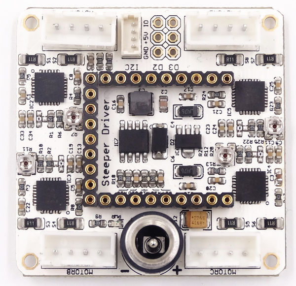
| + | [[File:Steppershieldfront.jpg|thumb|600px|center|Shield Stepper Front]] | ||
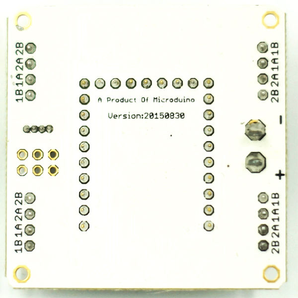
| + | [[File:Steppershieldback.jpg|thumb|600px|center|Shield Stepper back]] | ||
| + | |||
| + | ==Video== | ||
| + | |} | ||
Latest revision as of 20:54, 3 May 2017
| Language: | English • 中文 |
|---|
|
Microduino-Shield Stepper is a DMOS microstep driving plate with a transverter and overcurrent protection, which can drive a two phase stepping motor under the full, half, 1/4, 1/8 and 1/16 stepping mode, and can operate four motors at most at the same time.
Contents[hide]FeaturesStepping motor is a kind of electromagnetic device which can transform the pulse signal into corresponding angular displacement(or line displacement), and it is a special motor. Motors operate continuously generally, while the stepping motor has positioning and operating two basic states. When there is a pulse inputted, the stepping motor rotates step by step, and it can turn a fixed angle each time to give it a pulse signal.
Specification
Current limitation = VREG X 2.5 Therefor, if you want the motor coil to get 1A current, the current limitation should be 1A/0.7 = 1.4A, which is equivalent to VREF = 1.4A/2.5 = 0.56V. You should adjust the VREF voltage to 0.56V through adjusting the potentiometer.
Note: When the driver board has worked under a large current for a long time, the chip will be hot. If possible, you should add heat sink on it, to help the chip cool.
Document
【Shield Stepper schematic diagram】
DevelopmentIt is mainly used in the balanced car. Upin27 interface can be stacked with Microduino extension module to implement the second development.
Connect the stepping motor to the MotorA interface with 2.54 4pin connecting cable. The effect of the program is to make the stepping motor turn a angle, then stop for 500ms and then continue rotating toward. If you want to make it rotate reversely, you can cancel the comment part, and only keep the above two lines. //Claim the driving pin D5 , A0 and enable D4 of pin Motor1.
#define MOTOR_EN 4 //PORTB,0
#define MOTOR1_DIR A0 //PORTA,7
#define MOTOR1_STEP 5 //PORTB,1
void setup() {
// put your setup code here, to run once:
pinMode(MOTOR_EN, OUTPUT);
pinMode(MOTOR1_DIR, OUTPUT);
pinMode(MOTOR1_STEP, OUTPUT);
digitalWrite(MOTOR_EN, LOW); //Enable
}
void step(boolean dir, int steps) //Stepping function, the first variable is direction and the second is the number of the step, namely the angle that it turns.
{
digitalWrite(MOTOR1_DIR, dir);
delay(5);
for (int i = 0; i < steps; i++) {
digitalWrite(MOTOR1_STEP, HIGH);
delayMicroseconds(200);
digitalWrite(MOTOR1_STEP, LOW);
delayMicroseconds(200);
}
}
void loop() {
step(1, 1000); //Rotate forward
delay(500);
// step(0,1000); //Turn over
// delay(500);
}ApplicationOpen Source Self-balance Robot System PurchaseHistoryGalleryVideo |


