Difference between revisions of "CoreUSB Not Uploading Issue"
(→Guide for Microduino CoreUSB) |
(→Guide for Microduino CoreUSB) |
||
| Line 13: | Line 13: | ||
*Under Tools->Port, it should be un-selected. If it is selected please follow the guide '''[[CoreUSB_Not_Uploading_Issue#Deselecting_a_COM_Port|Deselecting a COM Port]]'''. Once completed. Restart this guide. | *Under Tools->Port, it should be un-selected. If it is selected please follow the guide '''[[CoreUSB_Not_Uploading_Issue#Deselecting_a_COM_Port|Deselecting a COM Port]]'''. Once completed. Restart this guide. | ||
*'''Read this step carefully!''' Your goal is to use something to connect two pins. Grab a metal paper clip or something conductive. If you have a jumper wire you can use that. You will need to create a connection between two pins -- RST and GND. See image which shows the labeling of the pins. Make sure your orientation is correct and that the pins are correct. Connecting other pins can potentially damage the board. | *'''Read this step carefully!''' Your goal is to use something to connect two pins. Grab a metal paper clip or something conductive. If you have a jumper wire you can use that. You will need to create a connection between two pins -- RST and GND. See image which shows the labeling of the pins. Make sure your orientation is correct and that the pins are correct. Connecting other pins can potentially damage the board. | ||
| − | |||
*Create the connection between the RST and GND pins: | *Create the connection between the RST and GND pins: | ||
#Wedge the paper clip between the two pins of the RST and GND pin. | #Wedge the paper clip between the two pins of the RST and GND pin. | ||
# '''OR''' Connect a jumper wire between the RST and GND pin. | # '''OR''' Connect a jumper wire between the RST and GND pin. | ||
| − | [[File:MD_CoreUSB_Fix2. | + | {| class="wikitable" |
| + | |+ Jumper Wire Method | ||
| + | |- | ||
| + | | [[File:MD_CoreUSB_Fix1.jpg|x300px]] | ||
| + | | [[File:MD_CoreUSB_Fix3.jpg|x300px]] | ||
| + | |} | ||
| + | |||
| + | {| class="wikitable" | ||
| + | |+ Paper Clip Method | ||
| + | |- | ||
| + | | [[File:MD_CoreUSB_Fix2.jpg|x300px]] | ||
| + | | [[File:MD_CoreUSB_Fix4.jpg|x300px]] | ||
| + | |} | ||
*With the paper clip still wedged or jumper wire still connected between the two pins. Go to the Microduino IDE and with the default blank sketch. Hit Upload (looks like a right arrow icon) on the top left. | *With the paper clip still wedged or jumper wire still connected between the two pins. Go to the Microduino IDE and with the default blank sketch. Hit Upload (looks like a right arrow icon) on the top left. | ||
*It should say "Compiling sketch..." near the bottom left of the IDE. If you can a compiling error. Hit upload again until you get "Compiling sketch..." followed by an "Uploading..." message. | *It should say "Compiling sketch..." near the bottom left of the IDE. If you can a compiling error. Hit upload again until you get "Compiling sketch..." followed by an "Uploading..." message. | ||
Revision as of 23:42, 5 December 2016
Microduino / mCookie CoreUSB sometimes encounters problems where the serial port is no longer detectable. This makes it impossible to upload new sketches to. This issue can occur quite often and is related to the software serial implementation of the chip.
Contents
Symptoms
When plugging in the Microduino / mCookie CoreUSB the COM port is temporarily available or even not detectable.
Possible Fix
If the problem is related to the COM (serial port). Then this fix might fix the problem.
Guide for Microduino CoreUSB
Please read all the steps below before performing the fix! Please contact Microduino Support if you have any questions
- Plug in the Microduino CoreUSB with a MicroUSB wire to your Computer. Have nothing else attached to the CoreUSB. Just the CoreUSB by itself!
- Open the Microduino IDE. Leave the default blank sketch open.
- Under Tools->Board, select Microduino/mCookie-Core USB.
- Under Tools->Processor, select USB.
- Under Tools->Port, it should be un-selected. If it is selected please follow the guide Deselecting a COM Port. Once completed. Restart this guide.
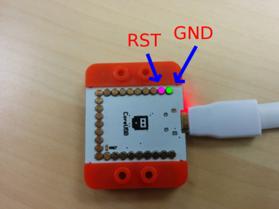
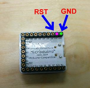
- Read this step carefully! Your goal is to use something to connect two pins. Grab a metal paper clip or something conductive. If you have a jumper wire you can use that. You will need to create a connection between two pins -- RST and GND. See image which shows the labeling of the pins. Make sure your orientation is correct and that the pins are correct. Connecting other pins can potentially damage the board.
- Create the connection between the RST and GND pins:
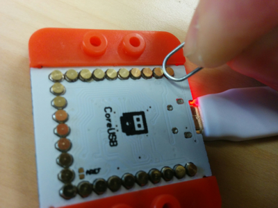
- Wedge the paper clip between the two pins of the RST and GND pin.
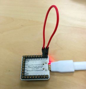
- OR Connect a jumper wire between the RST and GND pin.
|
|
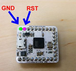
|
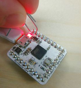
|
- With the paper clip still wedged or jumper wire still connected between the two pins. Go to the Microduino IDE and with the default blank sketch. Hit Upload (looks like a right arrow icon) on the top left.
- It should say "Compiling sketch..." near the bottom left of the IDE. If you can a compiling error. Hit upload again until you get "Compiling sketch..." followed by an "Uploading..." message.
- Once you see the "Uploading..." message. Remove the paper clip or jumper wire to disconnect the pins.
- If successful you should get a "Done uploading." message.
Guide for mCookie CoreUSB
Please read all the steps below before performing the fix! Please contact Microduino Support if you have any questions
- Plug in the mCookie CoreUSB with a MicroUSB wire to your Computer. Have nothing else attached to the CoreUSB. Just the CoreUSB by itself!
- Open the Microduino IDE. Leave the default blank sketch open.
- Under Tools->Board, select Microduino/mCookie-Core USB.
- Under Tools->Processor, select USB.
- Under Tools->Port, it should be un-selected. If it is selected please follow the guide Deselecting a COM Port. Once completed. Restart this guide.
- Read this step carefully! Grab a metal paper clip or something conductive. Your goal is to use something to connect two pins. A metal paperclip works really well here. You will need to create a connection between two pins -- RST and GND. See image which shows the labeling of the pins. Make sure your orientation is correct and that the pins are correct. Connecting other pins can potentially damage the board.
- Wedge the paper clip between the two circle pads of the RST and GND pin.
- With the paper clip still wedged between the two pins. Go to the Microduino IDE and with the default blank sketch. Hit Upload (looks like a right arrow icon) on the top left.
- It should say "Compiling sketch..." near the bottom left of the IDE. If you can a compiling error. Hit upload again until you get "Compiling sketch..." followed by an "Uploading..." message.
- Once you see the "Uploading..." message. Remove the paper clip to disconnect the pins.
- If successful you should get a "Done uploading." message.
Deselecting a COM Port
When attempting this fix. If you have a COM port select. This fix will not be successful. You will need to deselect the COM port following the steps below.
- Open the Microduino IDE.
- Arduino -> Preferences..
- At the bottom of the window. You should see "More preferences can be edited directly in the file." There should be a clickable file location under that. Click that. That will open a folder. Open the "preferences.txt"
- Close the Microduino IDE.
- Go back to the "preferences.txt" Scroll down to find the lines:
serial.port=***********
serial.port.file=***********
- Delete the values that are assigned to them so they will be
serial.port=
serial.port.file=
- Save the file. Re-open the Microduino IDE. Check under Tools->Port. There should be nothing selected. Bottom right of the IDE should say "Microduino/mCookie-Core USB (32u4), USB on"
- Restart the guide for your Microduino / mCookie CoreUSB
