Difference between revisions of "MCookie-GPS"
From Microduino Wiki
(→Specification) |
|||
| (4 intermediate revisions by the same user not shown) | |||
| Line 46: | Line 46: | ||
*Set baud rate through the two resistance on the module(R3 and R4, recommend 1k value): | *Set baud rate through the two resistance on the module(R3 and R4, recommend 1k value): | ||
{|class="wikitable" | {|class="wikitable" | ||
| − | ! rowspan="1" | R3 || R4 || Protocol ||Baud | + | ! rowspan="1" | R3 || R4 || Protocol|| Baud Rate |
| + | |- | ||
| Not weld || Not weld || NMEA || 9600 | | Not weld || Not weld || NMEA || 9600 | ||
|- | |- | ||
| − | | Not weld || Weld|| NMEA || 38400 | + | | Not weld ||Weld || NMEA || 38400 |
|- | |- | ||
| − | | Weld ||Not weld || NMEA || 4800 | + | | Weld || Not weld || NMEA || 4800 |
|- | |- | ||
| Weld || Weld || UBX || 57600 | | Weld || Weld || UBX || 57600 | ||
| Line 88: | Line 89: | ||
===Jumper Change=== | ===Jumper Change=== | ||
| − | *Players change module jumper by themselves:Cut off the wire on the center and the left of the two groups(D2 and D3) of bonding pad, and weld the middle and the right | + | *Players change module jumper by themselves:Cut off the wire on the center and the left of the two groups(D2 and D3) of bonding pad, and weld the middle and the right (RX0, TX1)of the bonding pad. |
| − | **If you has used the method of changing the jumper, you can connect Microduino NEO-6M with the serial port of the core, and change from TX-D2 and RX-D3 | + | **If you has used the method of changing the jumper, you can connect Microduino NEO-6M with the serial port of the core, and change from TX-D2 and RX-D3 to: TX-RX0, RX-TX1. |
**After changing the jumper, when downloading programs, please unplug Microduino NEO-6M module;or it will have a conflict with downloading programs. | **After changing the jumper, when downloading programs, please unplug Microduino NEO-6M module;or it will have a conflict with downloading programs. | ||
| Line 99: | Line 100: | ||
===Use Items of Library=== | ===Use Items of Library=== | ||
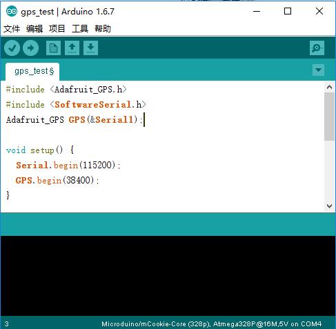
| − | *Open the | + | *Open the example"gps_test" program |
[[file:gps_test.jpg|thumb|600px|center]] | [[file:gps_test.jpg|thumb|600px|center]] | ||
| − | *Please confirm that the GPS module baud rate in void setup() is 38400, | + | *Please confirm that the GPS module baud rate in void setup() is 38400, namely:GPS.begin(38400); |
| − | *If you | + | *If you haven't altered the jumper wire on the reverse of the module: |
**When using Core+ to debug, you need to confirm that the program has the following definition:Adafruit_GPS GPS(&Serial1); | **When using Core+ to debug, you need to confirm that the program has the following definition:Adafruit_GPS GPS(&Serial1); | ||
| − | **When using Core to debug, you need to change | + | **When using Core to debug, you need to change "Adafruit_GPS GPS(&Serial1)" into "SoftwareSerial mySerial(3, 2); and Adafruit_GPS GPS(&mySerial);" |
| − | *If you have changed the jumper on the reverse of the | + | *If you have changed the jumper on the reverse of the module: |
| − | **When download programs, please unplug Microduino NEO-6M | + | **When download programs, please unplug Microduino NEO-6M module; |
| − | **When using Core or Core+ to debug, you need to confirm that the program has the following | + | **When using Core or Core+ to debug, you need to confirm that the program has the following definition: Adafruit_GPS GPS(&Serial); |
==Application== | ==Application== | ||
===Program Download=== | ===Program Download=== | ||
| − | The testing | + | The testing programs: '''[[File:Program Test mCookie-GPS.zip]]''' |
===Test Microduino NEO-6M Module=== | ===Test Microduino NEO-6M Module=== | ||
| − | *Hardware needs to be | + | *Hardware needs to be prepared: Microduino USBTTL, Microduino Core+, Microduino OLED, Microduino GPS; |
| − | *Software needs to be | + | *Software needs to be prepared: Arduino IDE(Version 1.0 and above), Adafruit_GPS library, and the testing programs (Arduino end)that Microduino provides; |
| − | *Environment need | + | *Environment need preparing: Open area, please don't test indoor. |
| − | *After downloading, | + | *After downloading, you'd better stack Microduino NEO-6M after cut off the electricity, to prevent stacking error , leading to short circuit and burn the modules. |
| − | *You can watch OLED after powering | + | *You can watch OLED after powering on: |
| − | **After about half a minute, the date and time will be displayed | + | **After about half a minute, the date and time will be displayed firstly; |
**Continue waiting. When you see the PPS indicator light is twinkling, the velocity, latitude and longitude indexes should be all displayed. If not, please restart Microduino Core. | **Continue waiting. When you see the PPS indicator light is twinkling, the velocity, latitude and longitude indexes should be all displayed. If not, please restart Microduino Core. | ||
| Line 134: | Line 135: | ||
| − | |||
| − | |||
==History== | ==History== | ||
Latest revision as of 03:25, 4 August 2017
|
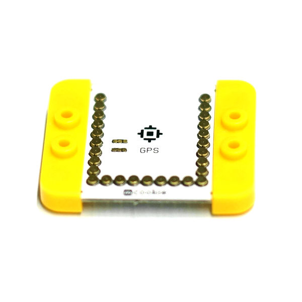
It may be the most beautiful GPS module that you have ever met. The core adopts UBLOX NEO-6M modules combination, which has high flexibility and the update rate can reach 5Hz. It adopts mini ceramic antenna of IPEX interface , and it has built-in rechargeable battery back-up.
ContentsFeatures
Specification
Description of Pins
PPS Status Indicator Lamp
DocumentsMain Component
Development*Please confirm whether the current of the +3.3v power supply can reach 200ma. It is not recommended that directly use the FT232R to debug, because the +3.3v current that FT232R outputs is too small. Jumper Change
Arduino Library and Support Package
Use Items of Library
ApplicationProgram DownloadThe testing programs: File:Program Test mCookie-GPS.zip Test Microduino NEO-6M Module
FAQ
PurchaseHistoryLibrary
Video |


