Difference between revisions of "Microduino-Module Motor"
From Microduino Wiki
| (2 intermediate revisions by 2 users not shown) | |||
| Line 24: | Line 24: | ||
*20 pins | *20 pins | ||
*4 mm×4mm×0.75mm size | *4 mm×4mm×0.75mm size | ||
| − | *With QFN package and naked pads | + | *With QFN package and naked pads to dissipate heat. |
*100% Matte tin plated pin | *100% Matte tin plated pin | ||
| Line 114: | Line 114: | ||
Test program:'''[[File:Program Test A3906.zip]]''' | Test program:'''[[File:Program Test A3906.zip]]''' | ||
| − | ===A3906 | + | ===A3906 controls two DB motors=== |
*Use Microduino core and Microduino A3906's control function; | *Use Microduino core and Microduino A3906's control function; | ||
*Prepared hardware: Microduino FT232R,Microduino Core, Microduino Motor and two DC motors as well as a power supply(2.5~9V); | *Prepared hardware: Microduino FT232R,Microduino Core, Microduino Motor and two DC motors as well as a power supply(2.5~9V); | ||
Latest revision as of 03:55, 4 August 2017
| Language: | English • 中文 |
|---|
|
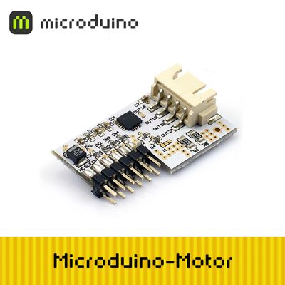
Microduino-Motor is a motor drive controller with the PWM control function. It can be used to control dual full bridge low voltage stepper motor, single or dual DC motor, widely applied in smart car and robot control.
ContentsFeature
Specification
Electrical specifications
Pin Description
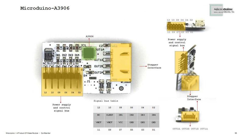
DocumentDriver chip:A3906 File:A3906-Datasheet.pdf DevelopmentDC motor wiringConnect one DC motor to OUT1A,OUT1B, the other to OUT2A,OUT2B. DC motor control mode
Step motor wiring
A and B group are absolute insulated and disconnected. Just use a multimeter to measure, the one connected belongs to one group.
Step motor control mode
ApplicationProgram downloadTest program:File:Program Test A3906.zip A3906 controls two DB motors
How to make a pegboard with Microduino core and Microduino Motor connected:
BugHistoryPicturesVideo |


