Difference between revisions of "Microduino-Module BLE"
(Created page with "{{Language|Microduino-【BT】}} {| style="width: 800px;" |- | 400px|thumb|right|Microduino-Shield BT4.0 Microduino-Shield BT 4.0 module is a p...") |
|||
| (37 intermediate revisions by 6 users not shown) | |||
| Line 1: | Line 1: | ||
| − | {{Language|Microduino- | + | {{Language|Microduino-BT}} |
{| style="width: 800px;" | {| style="width: 800px;" | ||
|- | |- | ||
| | | | ||
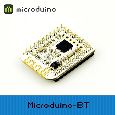
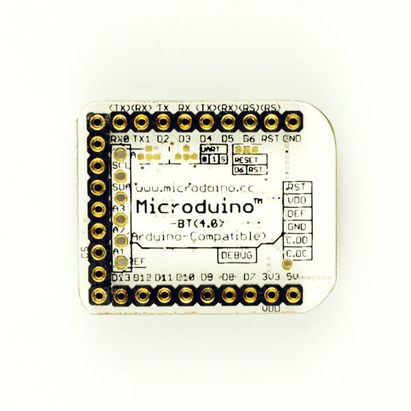
[[File:Microduino-bt-rect.jpg|400px|thumb|right|Microduino-Shield BT4.0]] | [[File:Microduino-bt-rect.jpg|400px|thumb|right|Microduino-Shield BT4.0]] | ||
| − | Microduino- | + | Microduino-BT is a BLE serial transparent transmission module based on CC2541 chip. It is custom-made for U-shaped 27PIN standard interface of Microduino. The old version can refer to [[Microduino-【BT】]]. |
| − | |||
| − | The | ||
==Features== | ==Features== | ||
| − | *Microduino | + | *Adopt Microduino UPIN27 standard interface, working by stacking with other Microduino modules; |
| − | + | *Adopt TI CC2541 chip with low consumption; | |
| − | *TI | + | *Support iBecons mode; |
| − | *Support AT instruction, | + | *Multiple ways to restore factory settings; |
| − | *Small, cheap, stackable; | + | **Use "AT+ RENEW\r\n" instruction to restore; |
| − | *Open source hardware circuit design | + | **Test pin DEF to GND and then power on the module. The LED light blinks after LED 1 keeps on for three seconds and meantime, loose DEF and factory reset succeeds, you can see the LED light blinks every one second. |
| − | * | + | *Capable of data power-off preservation function; |
| − | *2.54 pitch | + | *Support AT instruction and flexible to change serial baud rate, device name, code matching as well as other parameters according to various needs; |
| + | *Small, cheap, stackable and open source; | ||
| + | *Open source hardware circuit design and Arduino compatible programming development environment; | ||
| + | *Uniform Microduino interface standard and rich external modules, flexible to connect with other Microduino modules and sensors; | ||
| + | *2.54 pin pitch interface makes it easy to be integrated to pegboard. | ||
| − | == | + | ==Specification== |
| − | *Communication | + | *Way of Communication: Serial port transmission and the default serial port is D4(RX), D5(TX); |
| − | *Power | + | *Power Supply: +3.3VDC 50mA; |
| − | *Bluetooth | + | *Bluetooth Protocol: Bluetooth Specification V4.0 BLE; |
| − | *Service | + | *Service Support: Central & Peripheral UUID FFE0,FFE1; |
| − | * | + | *Frequency: 2.4GHz ISM band; |
| − | *Modulation | + | *Way of Modulation: GFSK(Gaussian Frequency Shift Keying); |
| − | *Power | + | *Transmit Power: ≤4dBm; |
| − | * | + | *Flexibility: ≤-84dBm at 0.1% BER; |
| − | *Transmission | + | *Transmission Rate: |
| − | **Asynchronous: 6 | + | **Asynchronous: 6 kbps; |
| − | **Synchronous: 6 | + | **Synchronous: 6 kbps; |
| − | * | + | *Status Indicator: |
| − | ** | + | **Before connection: |
| − | *** | + | ***Host machine indicator keeps on for 100ms every second when not recording slave machine address; |
| − | *** | + | ***Host machine indicator keeps on for 900ms every second when recording slave machine address; |
| − | * | + | ***Slave machine indicator keeps on for one second every two seconds. |
| + | **After connection: | ||
| + | **The indicator of both the host and the slave machine keeps on for 100ms every five seconds. | ||
| + | *During the transmission, each data package should include less than 120 bytes. The higher the baud rate is, the longer transmission interval is. There exists loss rate during Bluetooth data transmission. So users should be ready for re-transmission or data check. | ||
| + | *iBeacon has been integrated. Set by AT instruction "AT+MODE2\r\n" can be achieved only under slave machine. | ||
| + | **Work mode: 0(transmission), 1(Direct drive) and 2(iBeacon); | ||
| + | **iBeacon can be tested by Locate iBeacons offered on App Store. | ||
| − | == | + | ==Document== |
Eagle PCB '''[[File:Microduino-BT Shield.zip]]''' | Eagle PCB '''[[File:Microduino-BT Shield.zip]]''' | ||
| − | ===Main | + | Support AT instruction configuration/control: '''[[File:Microduino-BLE.pdf]]''' |
| − | * | + | |
| − | * | + | ===Main Components=== |
| + | *cc2541_datasheet:'''[[File:Cc2541.pdf]]''' | ||
| + | ===Android APP=== | ||
| + | *APP Installation package:'''[[File:BT APP.zip]]''' | ||
| + | *APP Source: https://github.com/iascchen/android-microduino | ||
| + | |||
| + | If you want to develop your own app referring to the android code in github, you need pay attention to that the UUID must be same with the UUID of Microduino-BT. | ||
| + | |||
| + | [[file:Microduino-BT-UUID.png|800px|thumb|center|Microduino-BT-UUID]] | ||
==Development== | ==Development== | ||
| − | ===Serial | + | ===Serial Port Communication Requirements=== |
| − | *Default serial | + | *Default serial configuration is: |
**Baud rate: 9600 | **Baud rate: 9600 | ||
**No check | **No check | ||
| − | **Data | + | **Data bit 8 |
| − | **Stop bit | + | **Stop bit 1 |
| − | * | + | *For Arduino IDE serial monitor: |
| − | **Set | + | **Set to: "\r\n", "9600baud" |
| − | *For other serial | + | *For other serial debugging software: |
| − | **Baud rate | + | **Baud rate 9600 |
**No check | **No check | ||
| − | **Data | + | **Data bit 8 |
| − | **Stop bit | + | **Stop bit |
| − | * | + | ===Use PC to Debug=== |
| − | **Microduino- | + | *Debug by serial port: |
| + | **Do not stack [[Microduino-USBTTL]] directly and cross connect RX(D4) and TX(D5) of [[Microduino-USBTTL]] and [[Microduino-BT]]. | ||
| + | {|class="wikitable" | ||
| + | |- | ||
| + | |Microduino-BT||Microduino-USBTTL | ||
| + | |- | ||
| + | |D4||TX1 | ||
| + | |- | ||
| + | |D5||RX0 | ||
| + | |- | ||
| + | |3V3 ||3V3 | ||
| + | |- | ||
| + | |GND ||GND | ||
| + | |- | ||
| + | |} | ||
| − | *Microduino Shield BT4.0 | + | ===Use USBTTL and Core to Download and Debug=== |
| + | *If it keeps using the default jumper (RX0, TX1): | ||
| + | **Unplug the Microduino Shield BT4.0 during downloading the program; | ||
| + | *If you want to change the jumper cables to meet your requirement, you need to cut the connection between two intermediate of the pad and RX0/TX1, and then connect them to D2, D3 (or D9, D10). | ||
| + | **If it needs to change the jumper, you can change the serial connection of Microduino Shield BT4.0 and Microduino Core from "TX-RX0, RX-TX1" to: | ||
| + | ***TX-D2, RX-D3 (For Core+'s Serial1) | ||
| + | ***TX-D9, RX-D10 (you can adopt SoftwareSerial library to solve the problem) | ||
| + | |||
| + | |||
| + | *Program | ||
| + | <source lang="cpp"> | ||
| + | //Use SoftwareSerial to use other soft serial ports. | ||
| + | #include <SoftwareSerial.h> | ||
| + | SoftwareSerial mySerial(4, 5); | ||
| + | |||
| + | #define my_Serial mySerial //Use soft serial ports 4 and 5. | ||
| + | //#define my_Serial Serial1 | ||
| + | String msg = ""; //To define a string. | ||
| − | + | void setup() | |
| − | + | { | |
| − | + | // Initialize the Bluetooth communication baud rate. | |
| + | my_Serial.begin(9600); | ||
| + | // Initialize the serial communication baud rate monitor. | ||
| + | Serial.begin(9600); | ||
| + | } | ||
| + | void loop() | ||
| + | { | ||
| + | //Every time receive a signal, feedback to the other end of the communication. | ||
| + | if (my_Serial.available() > 0) //If there are signals being transferred into the serial port. | ||
| + | { | ||
| + | msg = my_Serial.readStringUntil('\n'); //Get all the contents before the newline character. | ||
| + | Serial.println(msg); //The serial monitor displays the string received in the MSG. | ||
| + | my_Serial.println("^_^ Hello,Microduino!"); //Send data to the other end of Bluetooth communication. | ||
| + | } | ||
| + | } | ||
| + | </source> | ||
| − | === | + | ===Communicate with Android Device=== |
| − | * | + | *Only mobile phones with 4.3 and above system can communicate with Microduino-BT; |
| − | ** | + | *Download Android communication software, and install it to the mobile phone; |
| − | + | '''[[File:MSerial.zip]]''' | |
| − | * | + | |- |
| − | *** | + | | |
| − | *** | + | Step 1: Download programs to Microduino; |
| + | |- | ||
| + | | | ||
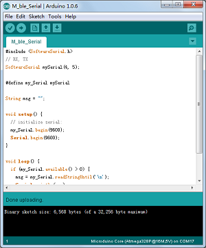
| + | [[File:ble-Download2.png|600px|center|thumb|Download]] | ||
| + | |||
| + | Step 2: Begin to set Android device. Open the bluetooth of the Android deice, open the App, and open the serial port monitor at the computer IDE; | ||
| + | |||
| + | Step 3: Click on the SCAN button at the top right corner of the App, which is used to search bluetooth access point around, and after clicking on the button, it will display surrounding bluetooth devices. | ||
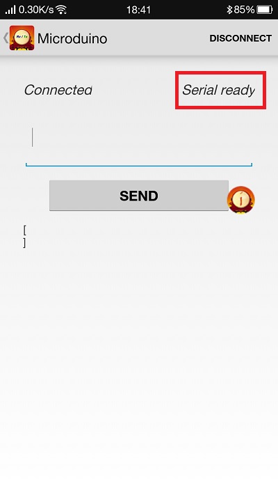
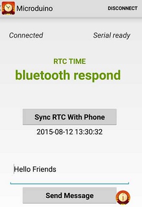
| + | Click the corresponding Microduino bluetooth number. After entering the interface, waiting about 2-3 seconds. When it changes into "Serial ready" on the top right corner of the screen, the mobile phone has been connected to the Bluetooth. | ||
| + | [[File:202KIT-android-ready.jpg|600px|center|thumb|App—mobile App]] | ||
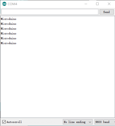
| + | The mobile sends English characters to Microduino, and the serial port monitor receives them. At the same time the mobile phone has received "^_^ Hello,Microduino!" that is sent by Microduino, which has proved the bidirectional communication function of Bluetooth. | ||
| + | [[File:microduino-android-system5.png|600px|center|thumb|App—Serial port monitor]] | ||
| + | [[File:202KIT-android-system6.jpg|600px|center|thumb|App—MobileApp]] | ||
| + | |||
| + | ===Communicate with IOS Device=== | ||
| + | *Above iPhone 4s, iPod touch 5, iPad 3, and iPad mini; | ||
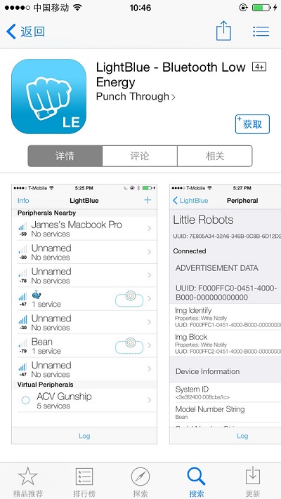
| + | *Go to App Store to download LightBlue: | ||
| + | |||
| + | [[File:LightBlue.jpg|400px|center|thumb|LightBlue]] | ||
| + | Step 1: Download the program to Microduino: | ||
| + | |||
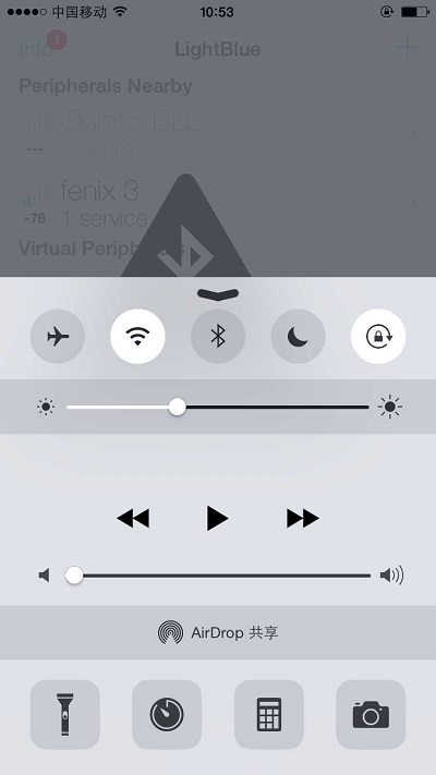
| + | Step 2: Install "lightblue". Open the software, and set the IOS device. Open the bluetooth of the IOS device. And open the serial port monitor on computer IDE. | ||
| + | [[File:LightBlue_on_ble.jpg|400px|center|thumb]] | ||
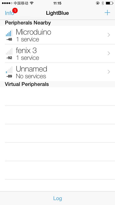
| + | Step 3: Open LightBlue: The interface that you have entered is bluetooth device searching interface. Find the bluetooth device of Microduino from the list under "Peripherals Nearby", and click it to connect it with the mobile phone; | ||
| + | |- | ||
| + | | | ||
| + | [[File:ble-Connection.jpg|400px|center|thumb|Connection1]] | ||
| + | After connecting, you will enter the interface as following: | ||
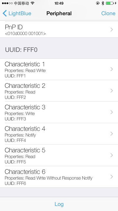
| + | [[File:ble-Connection1.jpg|400px|center|thumb|Connection2]] | ||
| + | |||
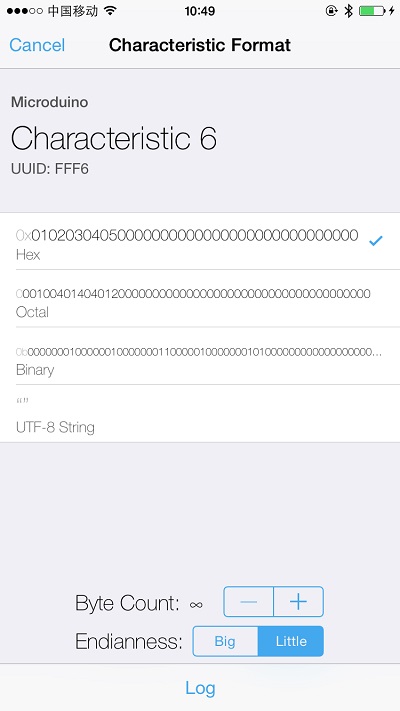
| + | Step 4: Choose and click Characteristic6, and look at the format of the code at the top right corner of the screen, and the default is Hex 16 binary code. If you want it displays the string, please click on the button where the Hex is and choose UTF-8 code format. Then click "Listen for notifications" to make the mobile phone into listening state. | ||
| + | [[File:ble-Connection5.jpg|400px|center|thumb]] | ||
| + | |||
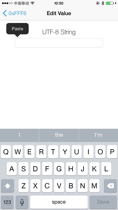
| + | Step 6: Click "Write new value", and the text editing interface will come out. | ||
| + | [[File:ble-Connection2.jpg|400px|center|thumb]] | ||
| + | Custom input a string of English and digital, and observe the result that the mobile and serial port display. | ||
| + | |||
| + | [[File:ble-Connection3.jpg|400px|center|thumb]] | ||
| + | [[File:ble-Connection4.jpg|400px|center|thumb]] | ||
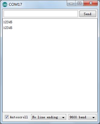
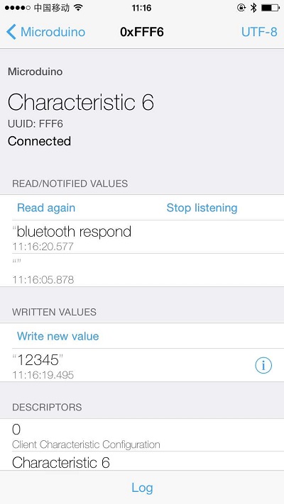
| + | You can see from the picture that the serials have received the "12345" that the mobile phone sent, and the mobile also has received the "bluetooth respond" that the bluetooth returned. It proves that the Bluetooth two-way communication is smooth. | ||
| + | |||
| + | ===Communicate with MAC Device=== | ||
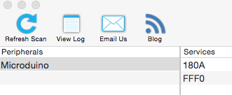
| + | mac bluetooth can't connect with BT search directly, so you need to use Light Blue to develop and download. | ||
| + | *Connect the Microduino-Core and BT module to the computer, and download the same code. | ||
| + | *Open the Arduino serial port monitor, then open Light Blue, and you will the Microduino device has been identified. | ||
| + | [[File:ble-Connection5.png|400px|center]] | ||
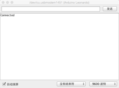
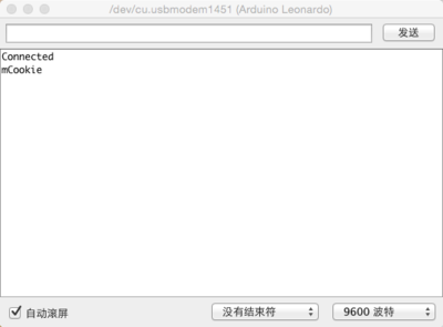
| + | *Click Microduino to connect with the bluetooth. After the connection, the serial port monitor will print out Connected. At the same time, the bluetooth indicator light will slightly twinkle(the frequency is mare faster, and the lightness is lower.). | ||
| + | [[File:ble-Connection6.png|400px|center]] | ||
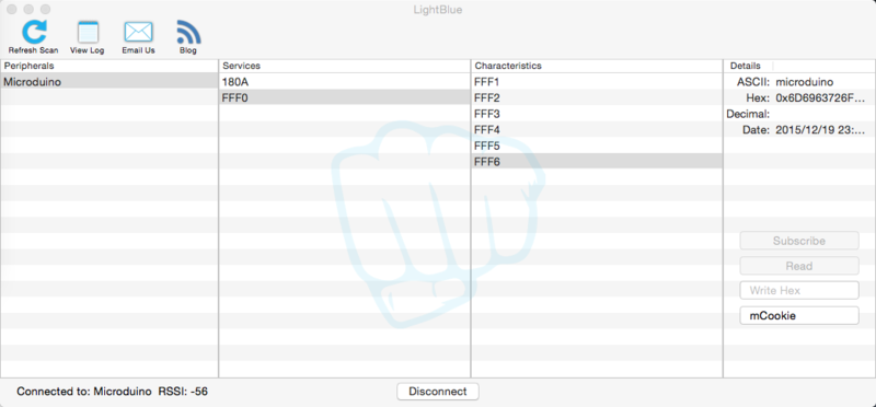
| + | *Choose as the following picture, and then send messages to BT module, such as mCookie. | ||
| + | [[File:ble-Connection7.png|800px|center]] | ||
| + | *YOu will see the serial port monitor prints Microduino. | ||
| + | [[File:ble-Connection8.png|400px|center]] | ||
| + | |||
| + | ==Extension== | ||
| + | ===Use AT to view or change the parameter of BT=== | ||
| + | *AT command configuration/Control document:'''[[File:Microduino-BLE.pdf]]''' | ||
| + | *Program | ||
| + | <source lang="cpp"> | ||
| + | //Use SoftwareSerial to use other soft serial ports. | ||
| + | //#include <SoftwareSerial.h> | ||
| + | //SoftwareSerial mySerial(4, 5); // RX, TX | ||
| + | |||
| + | //#define my_Serial mySerial | ||
| + | #define my_Serial Serial1 //Define serial ports CoreUSB and BT. | ||
| + | |||
| + | void setup() | ||
| + | { | ||
| + | Serial.begin(9600);//Serial communication baud rate monitor | ||
| + | my_Serial.begin(9600);//BT communication baud rate. | ||
| + | } | ||
| + | |||
| + | void loop() | ||
| + | { | ||
| + | if (Serial.available())//Monitor the data of the serial port monitor. | ||
| + | my_Serial.write(Serial.read());//Write data into BT. | ||
| + | if (my_Serial.available())//Monitor the data of BT serial port. | ||
| + | Serial.write(my_Serial.read());//Print the data in the serial port monitor. | ||
| + | } | ||
| + | </source> | ||
| + | *Program download | ||
| + | **Stack the mCookie-BT and mCookie-CoreUSB togethe. Insert the USB cable into the jack of mCookie-CoreUSB, and connect the other end to the USB port of the computer; | ||
| + | **Start Arduino IED, and copy the program to IDE; | ||
| + | **Choose Microduino CoreUSB at tools -> Board, and choose the corresponding serial port number at tools -> Serial; | ||
| + | **Click on the compile (√) at the top left corner of the IDE co compile the program. After finishing profiling, click the download (->) button to write the program to the board; | ||
| + | *Open the serial port monitor, and set it as: "\r\n", "9600baud". | ||
| + | [[File:ble-Serial.jpg|600px|center|thumb|Serial]] | ||
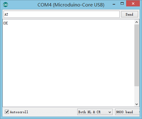
| + | *Input the specified commands in the serial port monitor, and you can see the result returned. And the reference document can change the parameter of BT. | ||
| + | [[File:ble-AT.jpg|600px|center|thumb|AT]] | ||
| + | |||
| + | Use software serial port communication program: | ||
| + | <source lang="cpp"> | ||
| + | //Use SoftwareSerial to use other soft serial ports. | ||
| + | #include <SoftwareSerial.h> | ||
| + | SoftwareSerial mySerial(4, 5);//According to the serial port selected, select the corresponding port numbers (2, 3) or (4, 5). | ||
| + | |||
| + | #define my_Serial mySerial | ||
| + | |||
| + | String msg = ""; | ||
| − | ===Pin | + | void setup() |
| + | { | ||
| + | //Initialize the Bluetooth communication baud rate. | ||
| + | my_Serial.begin(9600); | ||
| + | // Initialize the serial communication baud rate monitor. | ||
| + | Serial.begin(9600); | ||
| + | } | ||
| + | void loop() | ||
| + | { | ||
| + | //Every receiving the signal, feedback to the other end of the communication | ||
| + | if (my_Serial.available() > 0) //If there are data transferred into the serial ports. | ||
| + | { | ||
| + | msg = my_Serial.readStringUntil('\n'); //Get all the contents before the newline character. | ||
| + | Serial.println(msg); //The serial monitor displays the string received in the MSG. | ||
| + | my_Serial.println("bluetooth respond"); //Send data to the other end of the bluetooth communication. | ||
| + | } | ||
| + | } | ||
| + | </source> | ||
| + | ===Pin Description=== | ||
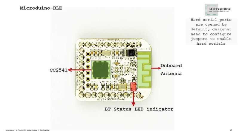
| − | :[[file:Microduino-BT- | + | :[[file:Microduino-BT-1Big2.jpg|800px|thumb|center|Microduino-BT]] |
<br style="clear: left"/> | <br style="clear: left"/> | ||
| − | :[[file:Microduino-BT- | + | :[[file:Microduino-BT-2Big1.jpg|800px|thumb|center|Microduino-BT]] |
<br style="clear: left"/> | <br style="clear: left"/> | ||
{|class="wikitable" | {|class="wikitable" | ||
| − | ! rowspan="1" | HM-10 | + | ! rowspan="1" | HM-10 module pin name || Microduino pin || Function |
|- | |- | ||
| − | | TX|| RX0(orD2/ | + | | TX|| RX0(orD2/D4) || Serial sending pin(TTL level), capable of connection RXD of a microcontroller. |
|- | |- | ||
| − | | RX || TX1(orD3/ | + | | RX || TX1(orD3/D5) || Serial receiving pin(TTL level), capable of connecting TXD of a microcontroller. |
|} | |} | ||
| + | ==Application== | ||
| + | ===Program Download=== | ||
| + | Program test: '''[[File:BLE debug uart1.zip]]''','''[[File:BLE LightBlue time.zip]]''' | ||
| − | * | + | ===Serial Port Debug Shield BT4.0 by CoreUSB === |
| + | *Hardware: Microduino CoreUSB and Microduino BT; | ||
| + | *Software: Arduino IDE (version 1.0 or higher) and Microduino test program (Arduino end); | ||
| + | **Other conditions: Users can change the jumpers back of the module and change the serial port to RX0(D0) and TX1(D1);(Because CoreUSB can use USB to simulate 0(Serial), and RX0 and TX1 is the (Serial 1) of CoreUSB); | ||
| + | *Start Arduino IDE, open Microduino test program and choose Microduino-CoreUSB as the board and download directly; | ||
| + | *Check if the serial communication is OK or not: | ||
| + | **Send "AT"(with \r\n behind) after opening the serial monitor and if the return is "OK", it means the configuration is successful. | ||
| − | == | + | ===Have serial debugging of BT module by uart1 of Core+ === |
| − | + | *Hardware: Microduino USBTTL, Microduino Core+ and Microduino BT; | |
| − | + | *Software: Arduino IDE (version 1.0 and higher) as well as Microduino test program (Arduino end); | |
| + | *Other conditions: Users can change the jumpers back of the module and change the serial port to D2 and D3; | ||
| + | *Start Arduino IDE, open Microduino test program and choose board Microduino Core+( Atmega644P@16M,5V) and download; | ||
| + | *Check the status of the serial communication: | ||
| + | ** Send "AT"(with \r\n behind) after opening the serial monitor and if the return is "OK", it means the configuration is successful. | ||
| − | + | [[Intercommunication between Two Microduino-BT Modules]] | |
| − | |||
| − | |||
| − | |||
| − | |||
| − | |||
| − | |||
| − | |||
| − | |||
| − | |||
| − | + | [[Microduino BT Serial port Transmits Data to IOS Device]] | |
| − | |||
| − | |||
| − | |||
| − | |||
| − | |||
| − | |||
| − | + | Note: If you use Android device to debug, you need to make sure the system should be version 4.3 or higher so that Microduino-BT can be detected. | |
| − | |||
| − | |||
| − | |||
| − | |||
| − | |||
| − | |||
| − | |||
| − | |||
===A simple test of Microduino-Shield BT4.0=== | ===A simple test of Microduino-Shield BT4.0=== | ||
*[http://viewc.com/p/296 A simple test of Microduino-Shield BT4.0] from @颜火山 | *[http://viewc.com/p/296 A simple test of Microduino-Shield BT4.0] from @颜火山 | ||
| − | == | + | ==FAQ== |
| − | * | + | *The module can't make pair with win7? |
| − | ** | + | **Please check its version in win 7, which only support BLE 4.0 version and the default password is 000000. |
| − | * | + | *How to reset the module? |
| − | ** | + | **You can adopt power-on reset or send AT instruction "AT+RESTART\r\n" through the serial port. |
| − | * | + | *It can't make pair with iPhone or Android phones? |
| − | **This issue mostly | + | **This issue is mostly caused by the version of the BT. This module only supports BT4.0 protocol. |
| − | **For Andriod OS: 4.3 | + | **For Andriod OS: 4.3 and higher |
| − | **For IOS: | + | **For IOS: iPhone 4s and higher, iPod Touch 5 and higher, iPad 3 and higher,iPad mini and higher. |
| − | == | + | |
| + | ==Purchase== | ||
==History== | ==History== | ||
| − | *On June 5, | + | *On July, 28, 2014, the module scheme was cancelled. The new BT version adopts CC25541 chip, supporting iBeacons mode. For the old version, you can refer to [[Microduino-【BT】]]. |
| − | *On May | + | *On June 5, 2014, the second proofing was finished, changing its name to <nowiki>Microduino-[BT]</nowiki> and add the third optional serial port—UART1. It is divided into two versions—version 2.1, a module used for HM09 and 4.0 version, a module used for HM10. |
| + | *On 10, May, 2013, the board design was finished. | ||
| + | |||
|- | |- | ||
| | | | ||
| + | |||
==Pictures== | ==Pictures== | ||
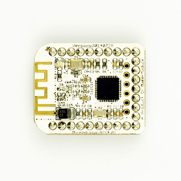
| − | [[file:Microduino- | + | [[file:Microduino-BT-t.jpg|thumb|600px|center|Microduino BT 4.0 Front]] |
| − | [[file:Microduino- | + | [[file:Microduino-BT-b.jpg|thumb|600px|center|Microduino BT 4.0 Back]] |
==Video== | ==Video== | ||
|} | |} | ||
Latest revision as of 04:22, 4 August 2017
| Language: | English • 中文 |
|---|
|
Microduino-BT is a BLE serial transparent transmission module based on CC2541 chip. It is custom-made for U-shaped 27PIN standard interface of Microduino. The old version can refer to Microduino-【BT】. ContentsFeatures
Specification
DocumentEagle PCB File:Microduino-BT Shield.zip Support AT instruction configuration/control: File:Microduino-BLE.pdf Main Components
Android APP
If you want to develop your own app referring to the android code in github, you need pay attention to that the UUID must be same with the UUID of Microduino-BT. DevelopmentSerial Port Communication Requirements
Use PC to Debug
Use USBTTL and Core to Download and Debug
//Use SoftwareSerial to use other soft serial ports.
#include <SoftwareSerial.h>
SoftwareSerial mySerial(4, 5);

#define my_Serial mySerial //Use soft serial ports 4 and 5.
//#define my_Serial Serial1
String msg = ""; //To define a string.

void setup()
{
  // Initialize the Bluetooth communication baud rate.
  my_Serial.begin(9600);
  // Initialize the serial communication baud rate monitor.
  Serial.begin(9600);
}
void loop()
{
  //Every time receive a signal, feedback to the other end of the communication.
  if (my_Serial.available() > 0)  //If there are signals being transferred into the serial port.
  {
    msg = my_Serial.readStringUntil('\n'); //Get all the contents before the newline character.
    Serial.println(msg);                   //The serial monitor displays the string received in the MSG.
    my_Serial.println("^_^ Hello,Microduino!");  //Send data to the other end of Bluetooth communication.
  }
}
Communicate with Android Device
File:MSerial.zip | ||||||||||
|
Step 1: Download programs to Microduino; | ||||||||||
|
Step 2: Begin to set Android device. Open the bluetooth of the Android deice, open the App, and open the serial port monitor at the computer IDE; Step 3: Click on the SCAN button at the top right corner of the App, which is used to search bluetooth access point around, and after clicking on the button, it will display surrounding bluetooth devices. Click the corresponding Microduino bluetooth number. After entering the interface, waiting about 2-3 seconds. When it changes into "Serial ready" on the top right corner of the screen, the mobile phone has been connected to the Bluetooth. The mobile sends English characters to Microduino, and the serial port monitor receives them. At the same time the mobile phone has received "^_^ Hello,Microduino!" that is sent by Microduino, which has proved the bidirectional communication function of Bluetooth. Communicate with IOS Device
Step 1: Download the program to Microduino: Step 2: Install "lightblue". Open the software, and set the IOS device. Open the bluetooth of the IOS device. And open the serial port monitor on computer IDE. Step 3: Open LightBlue: The interface that you have entered is bluetooth device searching interface. Find the bluetooth device of Microduino from the list under "Peripherals Nearby", and click it to connect it with the mobile phone; | ||||||||||
|
After connecting, you will enter the interface as following: Step 4: Choose and click Characteristic6, and look at the format of the code at the top right corner of the screen, and the default is Hex 16 binary code. If you want it displays the string, please click on the button where the Hex is and choose UTF-8 code format. Then click "Listen for notifications" to make the mobile phone into listening state. Step 6: Click "Write new value", and the text editing interface will come out. Custom input a string of English and digital, and observe the result that the mobile and serial port display. You can see from the picture that the serials have received the "12345" that the mobile phone sent, and the mobile also has received the "bluetooth respond" that the bluetooth returned. It proves that the Bluetooth two-way communication is smooth. Communicate with MAC Devicemac bluetooth can't connect with BT search directly, so you need to use Light Blue to develop and download.
ExtensionUse AT to view or change the parameter of BT
//Use SoftwareSerial to use other soft serial ports.
//#include <SoftwareSerial.h>
//SoftwareSerial mySerial(4, 5); // RX, TX

//#define my_Serial mySerial
#define my_Serial Serial1 //Define serial ports CoreUSB and BT.

void setup()
{
  Serial.begin(9600);//Serial communication baud rate monitor
  my_Serial.begin(9600);//BT communication baud rate.
}

void loop()
{
  if (Serial.available())//Monitor the data of the serial port monitor.
    my_Serial.write(Serial.read());//Write data into BT.
  if (my_Serial.available())//Monitor the data of BT serial port.
    Serial.write(my_Serial.read());//Print the data in the serial port monitor.
}
Use software serial port communication program: //Use SoftwareSerial to use other soft serial ports.
#include <SoftwareSerial.h>
SoftwareSerial mySerial(4, 5);//According to the serial port selected, select the corresponding port numbers (2, 3) or (4, 5).
#define my_Serial mySerial
String msg = "";
void setup()
{
//Initialize the Bluetooth communication baud rate.
my_Serial.begin(9600);
// Initialize the serial communication baud rate monitor.
Serial.begin(9600);
}
void loop()
{
//Every receiving the signal, feedback to the other end of the communication
if (my_Serial.available() > 0) //If there are data transferred into the serial ports.
{
msg = my_Serial.readStringUntil('\n'); //Get all the contents before the newline character.
Serial.println(msg); //The serial monitor displays the string received in the MSG.
my_Serial.println("bluetooth respond"); //Send data to the other end of the bluetooth communication.
}
}Pin Description
ApplicationProgram DownloadProgram test: File:BLE debug uart1.zip,File:BLE LightBlue time.zip Serial Port Debug Shield BT4.0 by CoreUSB
Have serial debugging of BT module by uart1 of Core+
Intercommunication between Two Microduino-BT Modules Microduino BT Serial port Transmits Data to IOS Device Note: If you use Android device to debug, you need to make sure the system should be version 4.3 or higher so that Microduino-BT can be detected. A simple test of Microduino-Shield BT4.0
FAQ
PurchaseHistory
| ||||||||||
PicturesVideo |
