Difference between revisions of "Template:Setup mBattery with Core (Windows)"
From Microduino Wiki
(Created page with "# Open the Microduino software. <br> thumb|75px|left<br clear=all> # Go to “Tools > Board” and select “Microduino/mCookie-device” <br> File:...") |
|||
| Line 4: | Line 4: | ||
# Only have the red Core module and yellow battery stacked. Then connect the MicroUSB to the yellow battery and the other end to your computer's USB port. <br> [[File:MBattery-b.jpg|thumb|left|400px]]<br clear=all> | # Only have the red Core module and yellow battery stacked. Then connect the MicroUSB to the yellow battery and the other end to your computer's USB port. <br> [[File:MBattery-b.jpg|thumb|left|400px]]<br clear=all> | ||
# Check if the red LED is lit on the yellow battery. This indicates the battery is ON and SUPPLYING power to the modules.<br> If there is no red LED lit, then press and hold the button on the yellow battery for a few seconds to turn it on. <br><b>Note</b>: Blinking blue LEDs indicates the battery is CHARGING ONLY. <b><pre style="color: red">IMPORTANT: The red LED must be on when programming or using your project.</pre></b>[[File:MBattery-t.jpg|thumb|left|400px]]<br clear=all> | # Check if the red LED is lit on the yellow battery. This indicates the battery is ON and SUPPLYING power to the modules.<br> If there is no red LED lit, then press and hold the button on the yellow battery for a few seconds to turn it on. <br><b>Note</b>: Blinking blue LEDs indicates the battery is CHARGING ONLY. <b><pre style="color: red">IMPORTANT: The red LED must be on when programming or using your project.</pre></b>[[File:MBattery-t.jpg|thumb|left|400px]]<br clear=all> | ||
| − | # Go to “Tools > Port” and select the port. It is usually the one that is select-able. | + | # Go to “Tools > Port” and select the port. It is usually the one that is select-able.<br> [[File:Software_Setup_Guide_Select_Port_Selection.png|frame|left]]<br clear=all> |
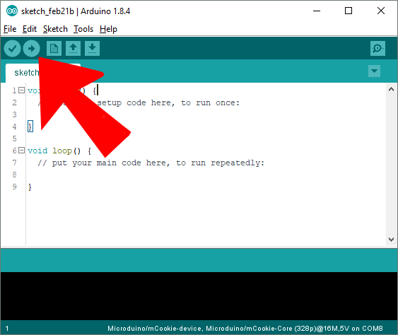
# With the default sample code. Hit upload (right arrow icon on the top left of the software). <br> [[File:Software_Setup_Guide_Select_Upload.png|frame|left]]<br clear=all> | # With the default sample code. Hit upload (right arrow icon on the top left of the software). <br> [[File:Software_Setup_Guide_Select_Upload.png|frame|left]]<br clear=all> | ||
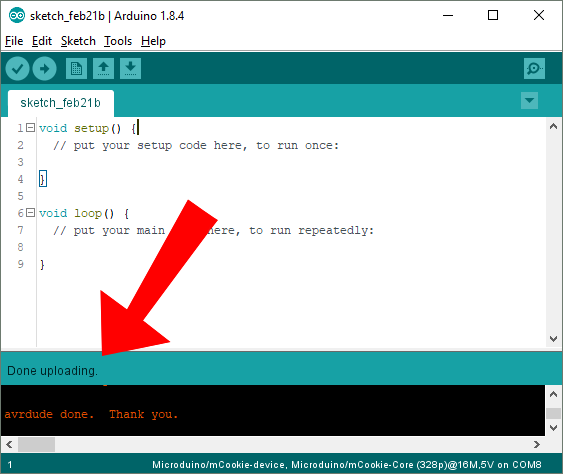
# The code will compile and will say upload complete if successful. Congratulations the software setup is complete! <br> [[File:Software_Setup_Guide_Select_Done_Upload.png|frame|left]]<br clear=all> | # The code will compile and will say upload complete if successful. Congratulations the software setup is complete! <br> [[File:Software_Setup_Guide_Select_Done_Upload.png|frame|left]]<br clear=all> | ||
Latest revision as of 18:07, 5 March 2018
- Open the Microduino software.
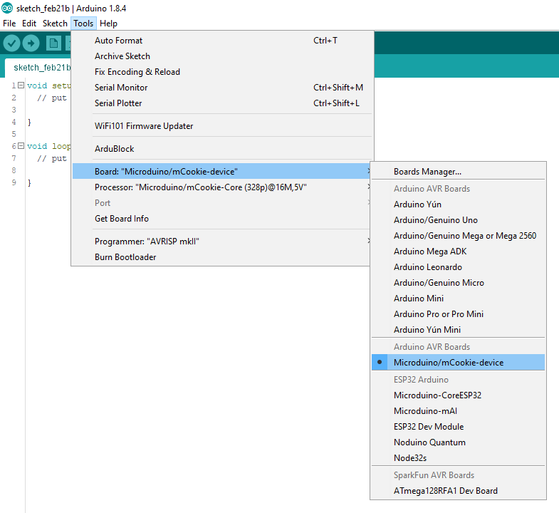
- Go to “Tools > Board” and select “Microduino/mCookie-device”
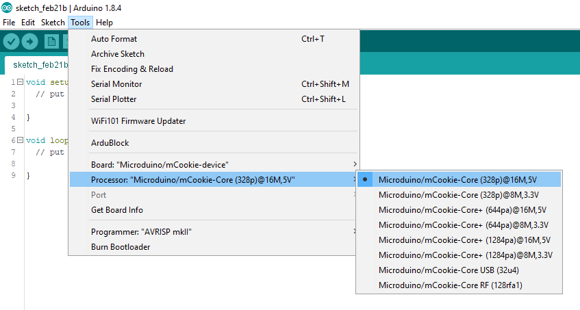
- Go to “Tools > Processor” and select “Microduino/mCookie-Core (328p)@16M,5V”
- Only have the red Core module and yellow battery stacked. Then connect the MicroUSB to the yellow battery and the other end to your computer's USB port.
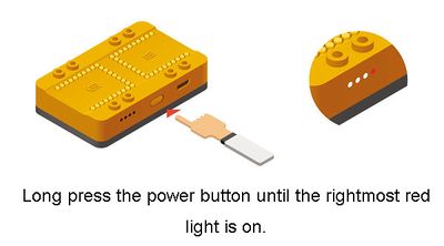
- Check if the red LED is lit on the yellow battery. This indicates the battery is ON and SUPPLYING power to the modules.
If there is no red LED lit, then press and hold the button on the yellow battery for a few seconds to turn it on.
Note: Blinking blue LEDs indicates the battery is CHARGING ONLY.IMPORTANT: The red LED must be on when programming or using your project.
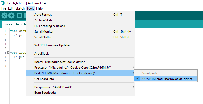
- Go to “Tools > Port” and select the port. It is usually the one that is select-able.
- With the default sample code. Hit upload (right arrow icon on the top left of the software).
- The code will compile and will say upload complete if successful. Congratulations the software setup is complete!
