Difference between revisions of "Microduino-Shield Cube-V1"
From Microduino Wiki
(→Features) |
(→Specifications) |
||
| Line 12: | Line 12: | ||
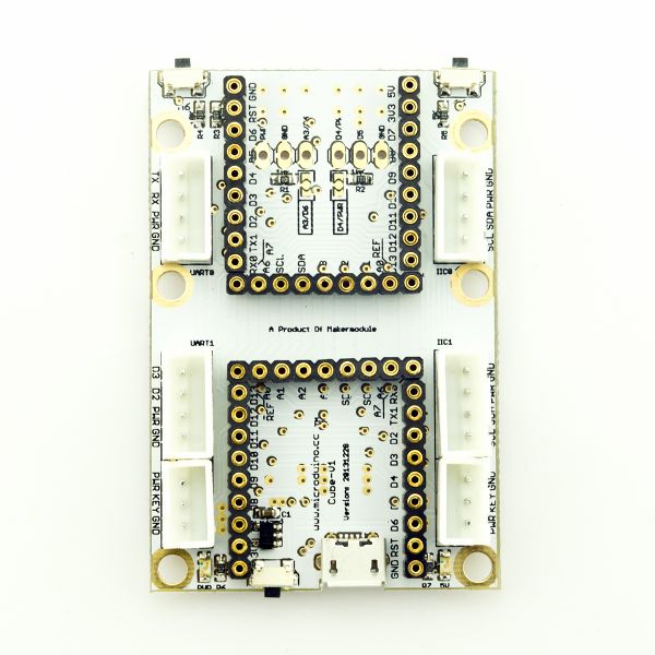
==Specifications== | ==Specifications== | ||
| − | *Electrical | + | *Electrical specification |
**MicroUSB power supply; | **MicroUSB power supply; | ||
| − | **3.3V | + | **3.3V constant voltage; |
| − | **Select the 5V or 3.3V power via PWR jumper | + | **Select the 5V or 3.3V power via PWR jumper.(The default voltage is 3.3V); |
| − | **Onboard power supply ( | + | **Onboard power supply indicator(5V and PWR); |
| − | * | + | *Extension |
**Onboard reset button; | **Onboard reset button; | ||
| − | **OLED | + | **Fixed OLED base; |
| − | **Two serial ports, | + | **Two serial ports including (RX0,TX0)and (D2,D3); |
**Two IIC interfaces; | **Two IIC interfaces; | ||
| − | **Two | + | **Two analog button interfaces connected to A7; |
| − | **Seven | + | **Seven analog buttons with two on the board connected to A6 and five on the stacking board connected to the interface of the base with Dupont lines; |
| − | ** | + | **Below are two groups of sensor interfaces which can be selected and combined through jumpers. Users can choose different jumper connection as they like: |
***PWR,GND,A3 or PWR,GND,A6; | ***PWR,GND,A3 or PWR,GND,A6; | ||
***PWR,D5,GND or D4,D5,GND。 | ***PWR,D5,GND or D4,D5,GND。 | ||
| Line 35: | Line 35: | ||
*Components | *Components | ||
| − | ** | + | **Base board:The board with two UPIN-27 standard interfaces; |
| − | **Overlay board: | + | |
| + | **Overlay board: The fixed board of five analog buttons and an OLED; | ||
[[file:Microduino-Cube--Pinout1-Pinout4.jpg|800px|thumb|center|Microduino-Cube-S1]] | [[file:Microduino-Cube--Pinout1-Pinout4.jpg|800px|thumb|center|Microduino-Cube-S1]] | ||
Revision as of 07:45, 15 August 2014
| Language: | English • 中文 |
|---|
ContentsFeatures
Specifications
DocumentEagle PCB local download Main components:
DevelopmentIt can be used with other Microduino modules, sensor to achieve specific functions. Application
BuyHistoryPictureFrontBackVideo |


