Difference between revisions of "Microduino Snake game"
From Microduino Wiki
(→Outline) |
|||
| (3 intermediate revisions by one other user not shown) | |||
| Line 4: | Line 4: | ||
| | | | ||
==Outline== | ==Outline== | ||
| − | * | + | *Project: Microduino Snake Game |
| − | * | + | *Objective: Connect the mobile and Microduino-Core by Microduino BT module, then control the double color LED lattice to play snake game! |
| − | * | + | *Difficulty: High |
| − | *Time- | + | *Time-consuming: 4 hours |
| − | * | + | *Maker: Microduino Studio-YLB |
First solution: | First solution: | ||
| Line 22: | Line 22: | ||
|Microduino-FT232R ||1||Download program | |Microduino-FT232R ||1||Download program | ||
|- | |- | ||
| − | |Microduino-BT ||1||Make | + | |Microduino-BT ||1||Make connection with mobile |
|} | |} | ||
*Other equipment | *Other equipment | ||
| Line 46: | Line 46: | ||
|} | |} | ||
| + | |||
==Document== | ==Document== | ||
| − | IIC lattice | + | IIC lattice chip: |
| − | + | Library: | |
==Debug== | ==Debug== | ||
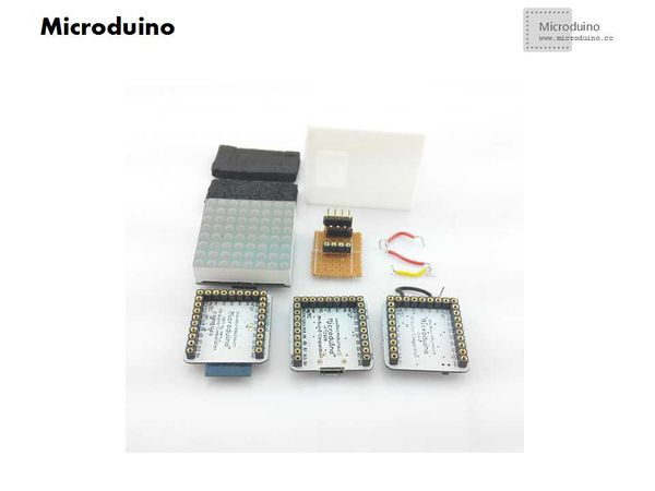
| − | *Step | + | *Step 1: Prepare the experiment equipment |
[[File:Microduino_Sneak_all.jpg||600px|center|thumb]] | [[File:Microduino_Sneak_all.jpg||600px|center|thumb]] | ||
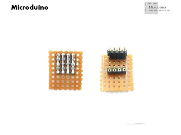
| − | * | + | *Step2: Build adapter board |
**Cut a certain specification size pegboard; | **Cut a certain specification size pegboard; | ||
| − | **Weld the row | + | **Weld the row needles; |
[[File:Microduino_Sneak_ok1.jpg||600px|center|thumb]] | [[File:Microduino_Sneak_ok1.jpg||600px|center|thumb]] | ||
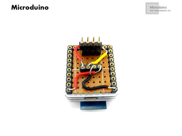
| − | **After finished | + | **After finished welding, use the bread board to make connection, From left to right in turn is the SDA and SCL, GND, VCC; |
[[File:Microduino_Sneak_ok2.jpg||600px|center|thumb]] | [[File:Microduino_Sneak_ok2.jpg||600px|center|thumb]] | ||
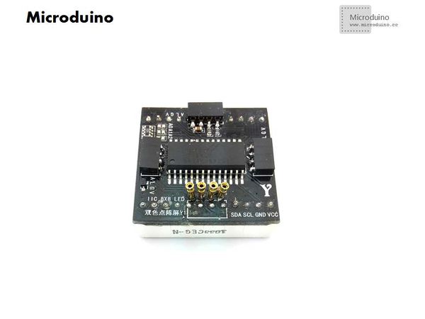
| − | *Step | + | *Step 3: Change the lattice, because the original LED lattice doesn't easy to connect the jumper, so change its row needles match Microduino's pin. |
[[File:Microduino_Sneak_writing.jpg||600px|center|thumb]] | [[File:Microduino_Sneak_writing.jpg||600px|center|thumb]] | ||
| − | *Step | + | *Step 4: Stack the module and lattice, measure the shell size. |
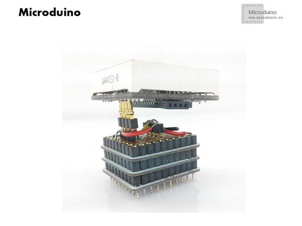
[[File:Microduino_Sneak_Combination.jpg||600px|center|thumb]] | [[File:Microduino_Sneak_Combination.jpg||600px|center|thumb]] | ||
| − | *Step | + | *Step 5: Draw the 3D shell |
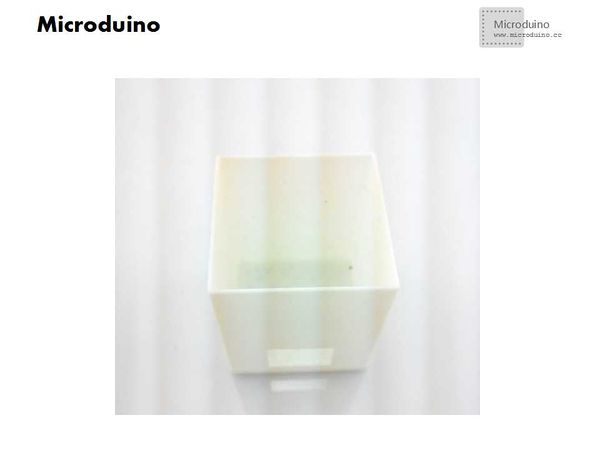
| − | *Step | + | *Step 6: Print 3D shell |
[[File:Microduino_Sneak_3D2.jpg||600px|center|thumb]] | [[File:Microduino_Sneak_3D2.jpg||600px|center|thumb]] | ||
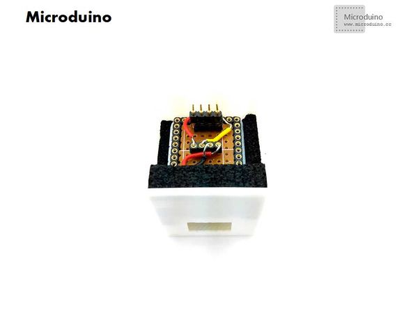
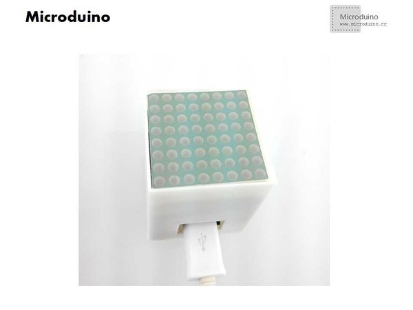
| − | *Step | + | *Step 7: Assembly, put all module into 3D shell |
[[File:Microduino_Sneak_3D4.jpg||600px|center|thumb]] | [[File:Microduino_Sneak_3D4.jpg||600px|center|thumb]] | ||
[[File:Microduino_Sneak_3D3.jpg||600px|center|thumb]] | [[File:Microduino_Sneak_3D3.jpg||600px|center|thumb]] | ||
| − | *Step | + | *Step 8: Software debug |
**Download the library and test program | **Download the library and test program | ||
| − | **Select the board and serial to download after compiled it. Note, program use | + | **Select the board and serial to download after compiled it. Note, program use software Serial to debug, Software Serial mySerial(9, 10). So need change the serial pin to D9,D10 on Microduino BT module, or change the code. |
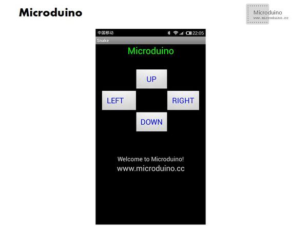
**Turn on the mobile BLE and APP, connect the Microduino and mobile, and then start to control. | **Turn on the mobile BLE and APP, connect the Microduino and mobile, and then start to control. | ||
[[File:Microduino_Sneak_android.jpg||600px|center|thumb]] | [[File:Microduino_Sneak_android.jpg||600px|center|thumb]] | ||
| Line 95: | Line 96: | ||
http://v.youku.com/v_show/id_XNjg0MDYwNzQw.html | http://v.youku.com/v_show/id_XNjg0MDYwNzQw.html | ||
| − | Second | + | Second solution: |
Use Microduino double color lattice. | Use Microduino double color lattice. | ||
==Advantage== | ==Advantage== | ||
| Line 111: | Line 112: | ||
|Microduino-FT232R ||1||Download program | |Microduino-FT232R ||1||Download program | ||
|- | |- | ||
| − | |Microduino-BT ||1||Make | + | |Microduino-BT ||1||Make connection with mobile |
|} | |} | ||
*Other equipment | *Other equipment | ||
| Line 133: | Line 134: | ||
==Debug== | ==Debug== | ||
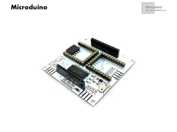
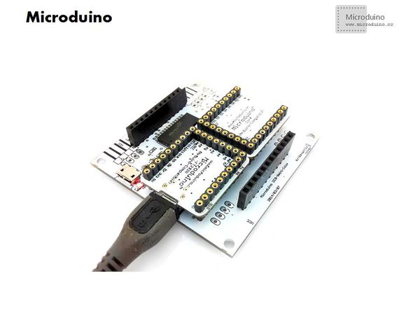
| − | *Step | + | *Step 1: Weld PCB |
[[File:Microduino_Sneak_LED_1.jpg||600px|center|thumb]] | [[File:Microduino_Sneak_LED_1.jpg||600px|center|thumb]] | ||
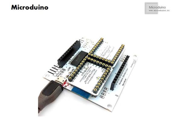
| − | *Step | + | *Step 2: Stack module |
[[File:Microduino_Sneak_LED_2.jpg||600px|center|thumb]] | [[File:Microduino_Sneak_LED_2.jpg||600px|center|thumb]] | ||
**Download library and test program | **Download library and test program | ||
**Turn on IDE, select the board and serial, download program after compiled it. | **Turn on IDE, select the board and serial, download program after compiled it. | ||
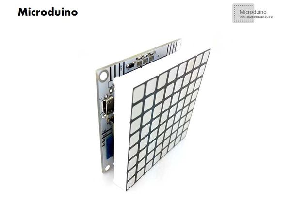
| − | *Step | + | *Step 3: Unplug the Microduino FT232 and plug in MIcrodino BT module. |
[[File:Microduino_Sneak_LED_3.jpg||600px|center|thumb]] | [[File:Microduino_Sneak_LED_3.jpg||600px|center|thumb]] | ||
*Plug in the lattice | *Plug in the lattice | ||
| Line 147: | Line 148: | ||
[[File:Microduino_Sneak_LED_5.jpg||600px|center|thumb]] | [[File:Microduino_Sneak_LED_5.jpg||600px|center|thumb]] | ||
**Rendering | **Rendering | ||
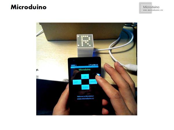
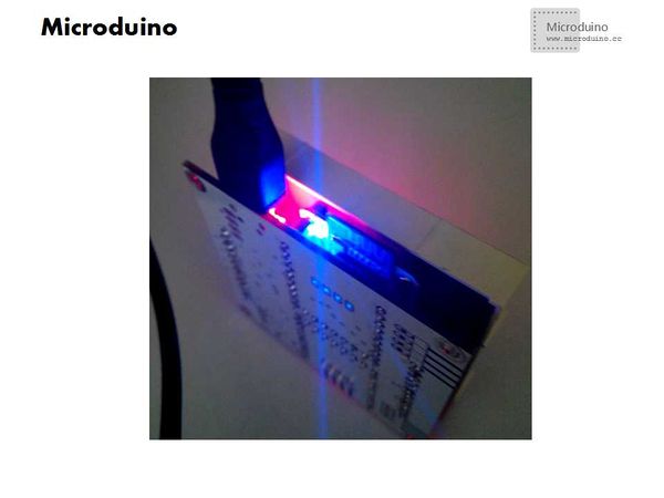
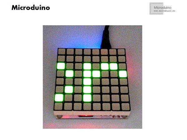
| − | Boot to display | + | Boot to display "Microduino": |
[[File:Microduino_Sneak_Effect_1.jpg||600px|center|thumb]] | [[File:Microduino_Sneak_Effect_1.jpg||600px|center|thumb]] | ||
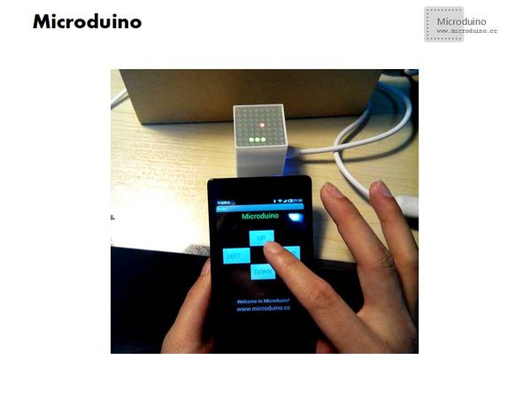
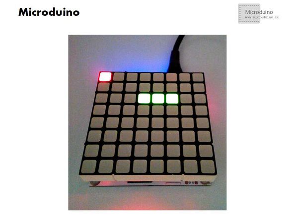
Start the game: | Start the game: | ||
| Line 153: | Line 154: | ||
==Result== | ==Result== | ||
| − | The | + | The use of Microduino lattice will achieve a better effect. |
| + | |||
==Video== | ==Video== | ||
http://v.youku.com/v_show/id_XNjkyNTY5MDky.html | http://v.youku.com/v_show/id_XNjkyNTY5MDky.html | ||
|} | |} | ||
Latest revision as of 09:23, 12 September 2016
| Language: | English • 中文 |
|---|
ContentsOutline
First solution: Bill of Materials
DocumentIIC lattice chip: Library: Debug
ResultBoot into the game after rolling Microduino, snake color is green, fruit is red. Because of the lattice is very small, won't increase the snake length, instead to increase the speed, and keep a certain high speed. When the snake hit the walls, show "GAMGOVER" and your scores, then restart again. The issue need pay attention
Videohttp://v.youku.com/v_show/id_XNjg0MDYwNzQw.html Second solution: Use Microduino double color lattice. Advantage
Bill of Materials
Debug
Boot to display "Microduino": Start the game: ResultThe use of Microduino lattice will achieve a better effect. Video |
