Difference between revisions of "Microduino-【BT】"
From Microduino Wiki
(→Pictures) |
(→Use Core32u4 to debug Shield BT4.0) |
||
| (36 intermediate revisions by 4 users not shown) | |||
| Line 1: | Line 1: | ||
| + | {{Language|Microduino-【BT】}} | ||
{| style="width: 800px;" | {| style="width: 800px;" | ||
|- | |- | ||
| | | | ||
| − | [[file:Microduino-bt-rect.jpg|400px|thumb|right|Microduino-【BT】]] | + | [[file:Microduino-bt -rect.jpg|400px|thumb|right|Microduino-【BT】]] |
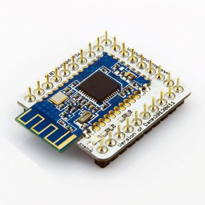
| − | + | Microduino-Shield BT 4.0 module is a plug-in device that supports Bluetooth 4.0 low energy standard. | |
| + | Microduino-Shield BT 4.0 module is a bluetooth serial port transparent transmission module, using the 27 PIN standard Microduino interface, supporting the Arduino board and derivatives, such as Microduino core. | ||
| + | The module is designed by player ogre_c. | ||
| − | + | ==Features== | |
| + | *Microduino-Shield BT4.0 adopts Upin27 interface of Microduino, combining with other Microduino modules to use; | ||
| + | *Microduino-Shield BT4.0 chooses the HM-10 BLE as the Bluetooth core module; | ||
| + | *TI CC2540 chip with 256Kb space and low power consumption; | ||
| + | *Support AT instruction, capable of updating baud rate, device name,paring code and other related parameters as needed, flexible to use; | ||
| + | *Small, cheap, stackable; | ||
| + | *Open source hardware circuit design, compatible with the Arduino IDE development environment for programming; | ||
| + | *With uniform Microduino interface standard and rich peripheral modules, it is flexible and convenient to have a quick connection and extension with other corresponding Microduino modules and sensors; | ||
| + | *2.54mm pin pitch for easy integration into breadboard. | ||
| + | |||
| + | ==Specifications== | ||
| + | *Communication form: serial transmission; | ||
| + | *Power supply:+3.3VDC 50mA; | ||
| + | *Bluetooth protocol:Bluetooth Specification V4.0 BLE; | ||
| + | *Service support:Central & Peripheral UUID FFE0,FFE1; | ||
| + | *Frequency:2.4GHz ISM band; | ||
| + | *Modulation mode:GFSK(Gaussian Frequency Shift Keying); | ||
| + | *Power of transmission:≤4dBm; | ||
| + | *Sensitivity:≤-84dBm at 0.1% BER; | ||
| + | *Transmission rate: | ||
| + | **Asynchronous: 6 kbps; | ||
| + | **Synchronous: 6 kbps; | ||
| + | *State indicator: | ||
| + | **Two states: | ||
| + | ***Flashing means that the module has been powered but not matched well. | ||
| + | ***Always lighting means that the module has been matched well and has started communication. | ||
| + | **By the indicator, it is very easy to the status of the module, which is conveniently. | ||
| + | |||
| + | ==Documents== | ||
| + | Eagle PCB '''[[File:Microduino-BT Shield.zip]]''' | ||
| + | |||
| + | ===Main component=== | ||
| + | **HM-10 Bluetooth module documentation:'''[[File:Bluetooth40 cn.pdf]]''','''[[File:Bluetooth40 en.pdf]]''' | ||
| + | **cc2540_datasheet:'''[[File:Cc2540 datasheet.pdf]]''' | ||
| + | |||
| + | ==Development== | ||
| + | ===Serial communication requirements=== | ||
| + | *Default serial configuration: | ||
| + | **Baud rate: 9600 | ||
| + | **No check | ||
| + | **Data bits: 8 | ||
| + | **Stop bit: 1 | ||
| + | *As for Arduino IDE serial monitor: | ||
| + | **Set at:"No line terminator"、"9600baud" | ||
| + | *For other serial debug software: | ||
| + | **Baud rate: 9600 | ||
| + | **No check | ||
| + | **Data bits: 8 | ||
| + | **Stop bit: 1 | ||
| − | + | *We suggest using Microduino-Core32u4 to debug this BT module: | |
| + | **Microduino-Core32u4 module can use the USB to simulate the serial 0, and BT uses the 32u4's serial 1 (RX0,TX1), so you don't need to change the existing jumper (RX0,TX1) and it won't impact program download or the serial port's function. | ||
| − | + | *Microduino Shield BT4.0 uses the default serial RX0,TX1 to communicate with Core module, so it can be directly connected with Microduino FT232. | |
| − | |||
| − | |||
| − | * | ||
| − | |||
| − | |||
| − | |||
| − | |||
| − | |||
| + | ===Use PC to debug=== | ||
| + | *When debugging directly through the serial port: | ||
| + | **No need to stack the FT232 directly, and just cross connect the FT232 and BT4.0's RX0,TX1. | ||
| − | + | ===Use FT232R、Core to download and debug=== | |
| − | + | *If it keeps using the default jumper (RX0、TX1): | |
| + | **Unplug the Microduino Shield BT4.0 during downloading the program; | ||
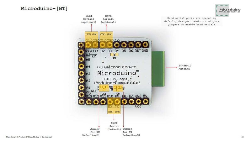
| + | *If you want to change the jumper cables to meet your requirement, you need to cut the connection between two intermediate of the pad and RX0/TX1, and then connect them to D2, D3(or D9、D10). | ||
| + | **If it needs to change the jumper, you can change the serial connection of Microduino Shield BT4.0 and Microduino Core from "TX-RX0、RX-TX1" to: | ||
| + | ***TX-D2、RX-D3 (For Core+'s Serial1) | ||
| + | ***TX-D9、RX-D10 (you can adopt SoftwareSeria libray to solve the problem) | ||
| − | == | + | ===Pin description=== |
| − | |||
| − | |||
| − | |||
| − | |||
| − | |||
| − | |||
| − | |||
| − | |||
| − | |||
| − | |||
| − | :[[file:Microduino-BT-1. | + | :[[file:Microduino-BT-1.jpg|800px|thumb|center|Microduino-BT]] |
<br style="clear: left"/> | <br style="clear: left"/> | ||
| − | :[[file:Microduino-BT-2. | + | :[[file:Microduino-BT-2.jpg|800px|thumb|center|Microduino-BT]] |
<br style="clear: left"/> | <br style="clear: left"/> | ||
| + | {|class="wikitable" | ||
| + | ! rowspan="1" | HM-10 Pin || Microduino Pin || Function | ||
|- | |- | ||
| − | | | + | | TX|| RX0(orD2/D9) || It serves as the serial transmission pin (TTL),capable of connecting the RXD of a microcontroller |
| + | |- | ||
| + | | RX || TX1(orD3/D10) || It serves as the serial receiving pin (TTL),capable of connecting the TXD of a microcontroller | ||
| + | |} | ||
| + | |||
| + | |||
| + | *Support AT intruction configuration and control:'''[[File:Bluetooth40 cn.pdf]]''','''[[File:Bluetooth40 en.pdf]]''' | ||
| − | == | + | ==Application== |
| − | + | ===Download progrm=== | |
| − | + | Program test:'''[[File:BLE debug uart1.zip]]''','''[[File:BLE LightBlue time.zip]]''' | |
| − | |||
| − | |||
| − | |||
| − | |||
| − | |||
| − | |||
| − | + | ===Shield BT4.0 pass-through data to IOS devices=== | |
| − | + | *Prepared hardware:Microduino FT232R, Microduino Core, Microduino Shield BT4.0, supported Bluetooth 4.0 devices (iPhone4s upper,iPod touch 5 upper,iPad 3 upper,iPad mini upper); | |
| + | *Prepared software: Arduino IDE (version 1.0 or higher), Microduino test program (Arduino part) and LightBlue downloaded from App Store; | ||
| + | *Start Arduino IED,open the Microduino test program, select board "Microduino Core (Atmega328P@16M,5V)" and then download directly; | ||
| + | *Start to set the IOS device: | ||
| + | **start Bluetooth on IOS device; | ||
| + | **Open LightBlue; | ||
| + | **Find the "HMSoft" in "Central" tab , then set "Service"-"Characteristics" in order; | ||
| + | **You can see the debugging window and then click the "Start Notify". | ||
| + | *ASCII data can be seen to be displayed: "BLE, Time: xxx". Besides, xxx shows the runtime of Microduino-Core and Shield BT4.0's in seconds. | ||
| − | == | + | ===Use Core32u4 to debug Shield BT4.0=== |
| − | * | + | *Hardware needed:Microduino FT232R,Microduino Core 32u4 and Microduino Shield BT4.0; |
| − | * | + | *Software needed:Arduino IDE(version 1.0 or higher), Microduino test program(Arduino part); |
| − | + | **(You can keep the current jumper(RXO,TX1) without change for Microduino-CoreUSb utilizes USB simulation port 0(Serial) and the RXO and TX1 of Microduino-BT are the serial1 of Microduino-CoreUSB; | |
| − | + | *Start Arduino IED, open Microduino test program, select Microduino-CoreUSB and then download; | |
| − | + | *Check whether the serial communication is ok: | |
| − | ** | + | **Send the capitalized "AT"(NO \r\n after it) after opening the corresponding serial monitor. And if the return shows "OK", it means the setup is successful. If you get a response "ERROR" then select "Both NL & CR" from the dropdown next to the baud rate in the serial monitor. |
| − | |||
| − | |||
| − | |||
| − | |||
| − | |||
| − | |||
| − | |||
| − | |||
| − | |||
| − | |||
| − | |||
| − | |||
| − | |||
| − | |||
| − | |||
| − | |||
| − | |||
| − | |||
| − | |||
| − | |||
| − | |||
| − | |||
| − | |||
| − | |||
| − | |||
| − | |||
| − | |||
| − | |||
| − | |||
| − | |||
| − | |||
| − | |||
| − | + | ===Use Core+'s uart1 to debug Shield BT4.0=== | |
| − | + | *Hardware needed:Microduino FT232R, Microduino Core+ and Microduino Shield BT4.0; | |
| − | + | *Software needed:Arduino IDE (version 1.0 or higher), Microduino test program (Arduino part); | |
| − | + | *Other condition:The player has changed the jumper, making the serial changed to D2、D3; | |
| + | *Start Arduino IED, open Microduino test program, select the board type "Microduino Core (Atmega328P@16M,5V)" and then download directly; | ||
| + | *Check the serial communication: | ||
| + | **Open the serial monitor,send the capitalized “AT”( without \r\n behind), if the return shows“OK”,that means a successful configuration. | ||
| − | + | ===[[How to Connect Two Microduino-BT Modules]]=== | |
| − | |||
| − | |||
| − | |||
| − | |||
| − | |||
| − | |||
| − | |||
| − | |||
| − | |||
| − | + | ===Note:If you use Android device to debug, you need to make sure the system should be version 4.3 or higher so that Microduino-BT can be detected.=== | |
| − | |||
| − | |||
| − | + | ===A simple test of Microduino-Shield BT4.0=== | |
| − | + | *[http://viewc.com/p/296 A simple test of Microduino-Shield BT4.0] from @颜火山 | |
| + | ==FQA== | ||
| + | *This module can’t make pair with win7? | ||
| + | **Check the BT version in win7, this module only support BLE 4.0 version and default password is 000000. | ||
| + | *Does this module can reset by button? | ||
| + | **No, it can be reset by power down. | ||
| + | *This module can’t make pair with iphone and Android phone? | ||
| + | **This issue mostly is caused by the BT version. This module only supports BT4.0 protocol. | ||
| + | **For Andriod OS: 4.3 release | ||
| + | **For IOS: iPhone4s upper, iPod touch 5 upper, iPad 3 upper and iPad mini upper | ||
==Buy== | ==Buy== | ||
| − | |||
| − | |||
| − | |||
==History== | ==History== | ||
| − | + | *On June 5, 2013, the second time proofing is completed, changed its name to the "Microduino - (BT)" and added the third optional serial port - UART1, divided into 2 version, version 2.1, a module used for HM09;A 4.0 version, module used for HM10. | |
| + | *On May 10, 2013, the board is completed. | ||
|- | |- | ||
| | | | ||
==Pictures== | ==Pictures== | ||
| − | [[file:Microduino-【BT】- | + | [[file:Microduino-【BT】-t.jpg|thumb|600px|center|Microduino BT 4.0 Front]] |
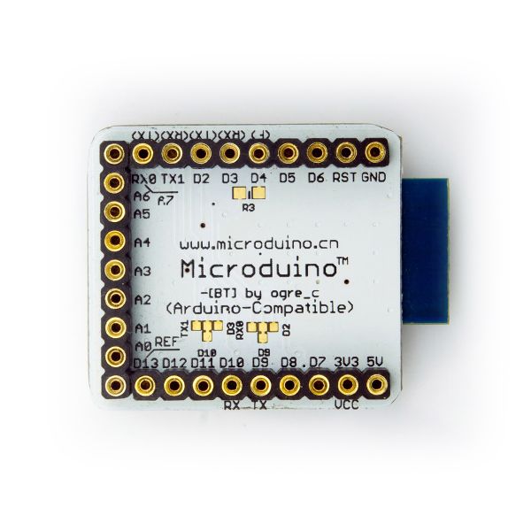
| − | [[file:Microduino-【BT】- | + | [[file:Microduino-【BT】-b.jpg|thumb|600px|center|Microduino BT 4.0 Back]] |
| − | |||
| + | ==Video== | ||
|} | |} | ||
Latest revision as of 09:57, 13 March 2015
| Language: | English • 中文 |
|---|
|
Microduino-Shield BT 4.0 module is a plug-in device that supports Bluetooth 4.0 low energy standard. Microduino-Shield BT 4.0 module is a bluetooth serial port transparent transmission module, using the 27 PIN standard Microduino interface, supporting the Arduino board and derivatives, such as Microduino core. The module is designed by player ogre_c. Contents
Features
Specifications
DocumentsEagle PCB File:Microduino-BT Shield.zip Main component
DevelopmentSerial communication requirements
Use PC to debug
Use FT232R、Core to download and debug
Pin description
ApplicationDownload progrmProgram test:File:BLE debug uart1.zip,File:BLE LightBlue time.zip Shield BT4.0 pass-through data to IOS devices
Use Core32u4 to debug Shield BT4.0
Use Core+'s uart1 to debug Shield BT4.0
How to Connect Two Microduino-BT ModulesNote:If you use Android device to debug, you need to make sure the system should be version 4.3 or higher so that Microduino-BT can be detected.A simple test of Microduino-Shield BT4.0
FQA
BuyHistory
| |||||||||
PicturesVideo |


