Difference between revisions of "Microduino-Joypad Getting start"
From Microduino Wiki
(→Body Feeling Configuration) |
|||
| (24 intermediate revisions by 5 users not shown) | |||
| Line 1: | Line 1: | ||
| + | |||
| + | {{Language|Microduino-Joypad Getting start}} | ||
{| style="width: 800px;" | {| style="width: 800px;" | ||
|- | |- | ||
| | | | ||
| − | == | + | ==Introduction & Overview== |
| − | * | + | *Editor:@Laopan |
| − | * | + | ===Background=== |
| − | * | + | *Joypad perhaps is born for rc controller. |
| − | * | + | *Joypad can remotely control not only the Robot, but also the quadrotor. |
| − | * | + | *It can support for multiple communication methods through stacking different Microduino modules . |
| − | * | + | *It can also configure a variety of function through the TFT color screen. |
| − | * | + | *Hope you can read this tutorial, and use Joypad to play your robot, little car, and quadrotor. |
| − | * | + | ===Bill of Modules=== |
| − | * | + | |
| + | {|class="wikitable" | ||
| + | |- | ||
| + | |Component||Number||Function | ||
| + | |- | ||
| + | |Joypad mainboard||1||Mainboard | ||
| + | |- | ||
| + | |Core module||1||The core | ||
| + | |- | ||
| + | |Communication module||1||To communicate | ||
| + | |- | ||
| + | |TFT screen||1||To display | ||
| + | |} | ||
| + | |||
| + | *The freedom degree of the Joypad is very high, and you can just choose core and modules according to the required functionality. | ||
| + | *YOu can refer to the following function/compatibility to choose the corresponding core module, communication module, and function modules. | ||
| + | **Joypad is compatible with any core except [[Microduino-CoreUSB]]. | ||
| + | {|class="wikitable" | ||
| + | | align="center" style="background:#f0f0f0;"|'''【Function】module/【Function】core''' | ||
| + | | align="center" style="background:#f0f0f0;"|'''【Don’t support communication】 Core''' | ||
| + | | align="center" style="background:#f0f0f0;"|'''【Don’t support communication】 Core+''' | ||
| + | | align="center" style="background:#f0f0f0;"|'''【Communication/Quadrotor】 CoreRF''' | ||
| + | |- | ||
| + | | '''【Communication/Robot】''' nRF||YES||YES||YES | ||
| + | |- | ||
| + | | '''【Communication/Quadrotor】''' BLE||YES||YES||NO | ||
| + | |- | ||
| + | | '''【Somatosensory】''' Motion||NO||YES||YES | ||
| + | |} | ||
| − | + | ===Modules Selection=== | |
| + | *Application scenarios:'''Control Robot remotely''' | ||
| + | **Use Core as the core module. | ||
| + | **Use nRF as the communication module. | ||
| − | + | *Application scenarios:'''Control Quadrotor remotely''' | |
| − | * | + | **Use CoreRF as the core module. |
| − | ** | + | **The core brings 2.4G communication function with it, so it needs no other core to cooperate with it. |
| − | |||
| − | |||
| − | |||
| − | |||
| − | |||
| − | |||
| − | |||
| − | |||
| − | |||
| − | |||
| − | ** | + | *Application scenarios:'''Body feeling control Quadrotor remotely''' |
| − | + | **Use CoreRF as the core module. | |
| + | **The core brings 2.4G communication function with it, so it needs no other core to cooperate with it. | ||
| + | **Use Motion as the body feeling module. | ||
| − | |||
| − | |||
| − | |||
| − | + | *Application scenarios:'''Body feeling control Robot remotely''' | |
| − | + | **Use Core+ as the core module. | |
| − | + | **Use nRF as the communication module. | |
| − | + | **Use Motion as the body feeling module. | |
| − | |||
| − | + | ===Bill of Material=== | |
| + | {|class="wikitable" | ||
| + | |- | ||
| + | |Component||Number||Function | ||
| + | |- | ||
| + | |Joypad panel||1||Panel | ||
| + | |- | ||
| + | |Nylon screw||8||To fix | ||
| + | |- | ||
| + | |Nylon nut||8||To fix | ||
| + | |- | ||
| + | |Nylon column||8||To fix | ||
| + | |- | ||
| + | |White button cap||4||Buttons | ||
| + | |- | ||
| + | |Rocker||2||Rockers | ||
| + | |- | ||
| + | |1.27mm 8P connecting line||1||To connect the TFT screen | ||
| + | |- | ||
| + | |10440 3.7v lithium battery(optional)||1||Power supply | ||
| + | |- | ||
| + | |Micro-USB cable(optional)||1||Program download | ||
| + | |} | ||
| − | |||
| − | |||
| − | |||
| − | |||
| − | |||
| − | |||
| − | |||
| − | |||
| − | |||
| − | |||
| − | |||
| − | |||
| − | |||
| − | |||
| − | |||
| − | |||
| − | |||
| − | |||
| − | |||
| − | |||
| − | |||
| − | |||
| − | |||
| − | |||
| − | |||
| − | |||
| − | |||
| − | |||
| − | |||
| − | + | ==Step-1 Programming== | |
| − | + | ===Download the Source Code=== | |
| − | + | At first download the program from the following address | |
| − | + | '''[[https://github.com/wasdpkj/Joypad_RC/ Joypad_RC]]''' | |
| − | + | ===Stack Modules=== | |
| − | + | *Use cable to connect [[Microduino-USBTTL]], and stack it together with your core to prepare to upload the program. | |
| − | + | **Note:You’d better upload the program before stacking all modules together. | |
| − | + | ===Configure the Environment=== | |
| + | *Open Arduino IDE for Microduino environment(Reference for setting up:'''[[AVR Core:Getting started]]''') | ||
| + | *Confirm the “board card” and“processor” is chosen correctly, and choose the corresponding port number (COMX). | ||
| − | + | ===Program Download=== | |
| − | + | *Open the “Joypad_RC.ino” program in the programs that you have downloaded. | |
| − | + | *Click "→" to download the program to the development board. | |
| − | |||
| − | == | ||
| − | * | ||
| − | * | ||
| − | |||
| − | + | ==Step-2 Reference Voltage== | |
| − | * | + | *In order to fitting for the input devices of Core and Joypad under any voltage:Rocker and the reference voltage of the switch are adjustable. |
| − | + | **If you have chosen CoreRF or the Core with 3.3V power source such as Core 3.3V and Core+ 3.3V. | |
| − | ** | + | **You need to reset the reference voltage of the mainboard of Joypad through the jumpers. |
| − | |||
| − | |||
| − | ** | ||
| − | |||
| − | |||
| − | * | + | ==Step-3 Battery powered== |
| − | + | ===Specifications of the Supported Battery=== | |
| − | + | *The specifications of the batteries that are supported is as following | |
| + | {|class="wikitable" | ||
| + | | align="center" style="background:#f0f0f0;"|'''Function/Type of battery''' | ||
| + | | align="center" style="background:#f0f0f0;"|'''10440 lithium battery (3.7V)''' | ||
| + | | align="center" style="background:#f0f0f0;"|'''AAA battery(1.5V)''' | ||
| + | |- | ||
| + | | Whether to support one piece||YES||NO | ||
| + | |- | ||
| + | | Whether to support two pieces||YES||YES | ||
| + | |- | ||
| + | | Whether to support charging||YES||NO | ||
|} | |} | ||
| + | |||
| + | |||
| + | *'''We recommend to use 10440 lithium battery(3.7V)''' | ||
| + | |||
| + | ===Active the Power Management Circuit=== | ||
| + | |||
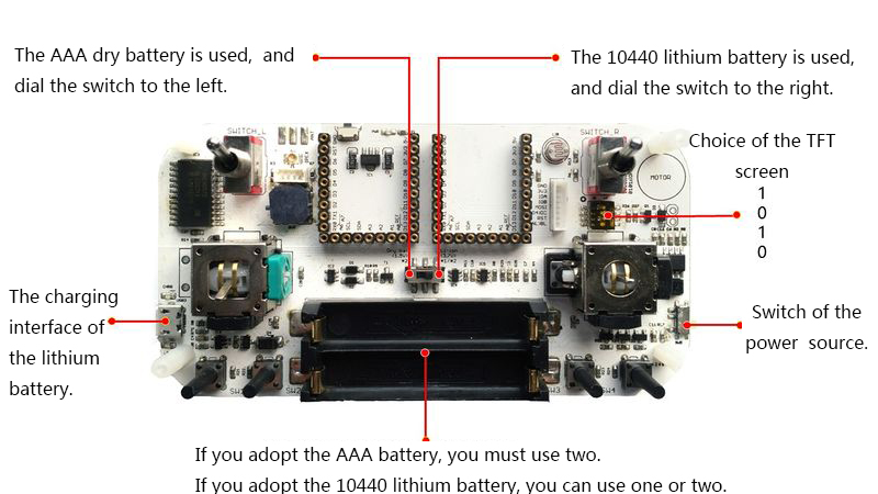
| + | *'''Referring to the following picture, according to the use of the battery, switch the battery mode switch to the correct position before access to the battery'''. | ||
| + | [[File:Joypadstep1_1.jpg|center|800px]] | ||
| + | |||
| + | *After connecting the battery, you must plug the USB, to '''active''' the battery management circuit of Joypad. | ||
| + | *After activing, you can control the power source switch of Joypad. | ||
| + | |||
| + | ===Electric Quantity Reminding and Charging(Limited to the 10440 Lithium Battery)=== | ||
| + | *'''When you use two 7 batteries,you can’t use USB to charge, and it will destroy the battery''' | ||
| + | *When the LOW indicator light lights close to the USB, the electric quantity of the battery is insufficient. | ||
| + | **'''When you use AAA battery, the light will be lighting all the time due to the insufficient voltage.''' | ||
| + | *Plug the USB, then it begins to charge. | ||
| + | *The CHRG indicator lamp close to the USB will light when charging, and the brightness will be lower or go out when the battery is fully charges. | ||
| + | ==Step-4 Assembly== | ||
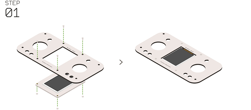
| + | *'''Step 1''': | ||
| + | *Clip Microduino-TFT in the Microduino-Joypad panel from the back. | ||
| + | *Use '''nylon screws''' and '''nylon nuts''' to fix, and pay attention to the installing direction of Microduino-TFT. | ||
| + | [[File:Joypadstep1.jpg|center|800px]] | ||
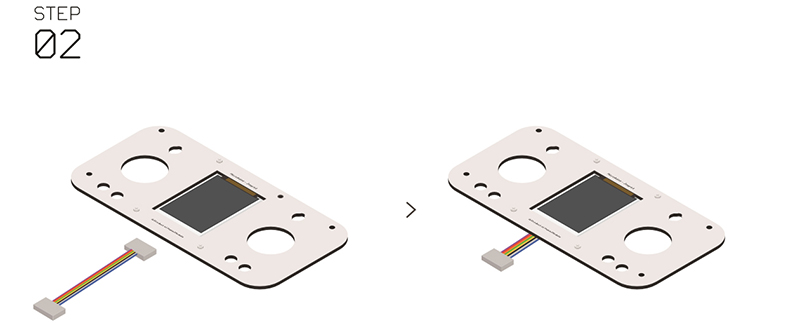
| + | *'''Step 2''': | ||
| + | *Inset lines to the Microduino-TFT. | ||
| + | [[File:Joypadstep2.jpg|center|800px]] | ||
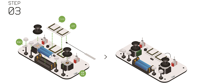
| + | *'''Step 3''': | ||
| + | *Install the communication module and the core module to the UPIN27 interface of the baseboard of the Joypad. | ||
| + | *Confirm that the “battery”, the" two rocker caps", and the "four white keys" have been installed to the corresponding position. | ||
| + | [[File:Joypadstep3.jpg|center|800px]] | ||
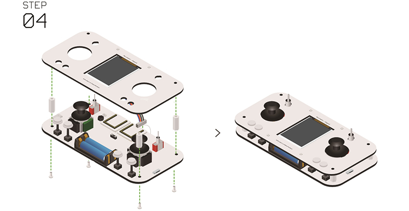
| + | *'''Step 4''': | ||
| + | *Connect the other end of the line in Microduino-TFT to the corresponding interface in the baseboard. | ||
| + | *Make the eight '''nylon columns''' connected between every two and to make up an extended edition. | ||
| + | *Use '''nylon nuts ''' to fix the extended edition of '''nylon column''' on the four corners of the baseboard. | ||
| + | [[File:Joypadstep4.jpg|center|800px]] | ||
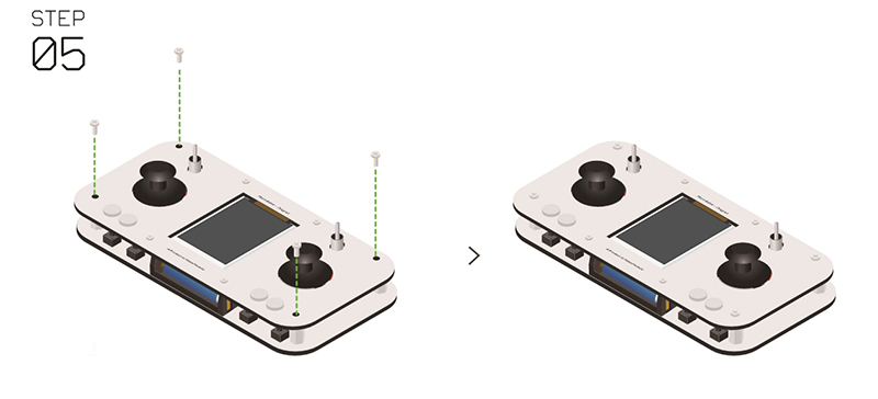
| + | *'''Step 5''': | ||
| + | *Use '''nylon screws''' to fix the four corners of the panel. | ||
| + | [[File:Joypadstep5.jpg|center|800px]] | ||
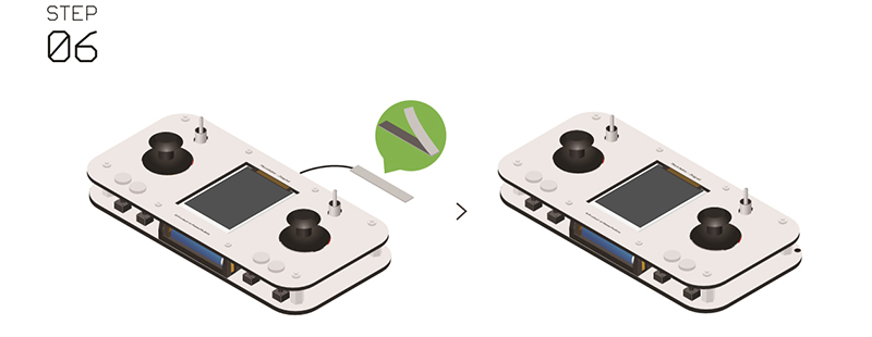
| + | *'''Step 6''': | ||
| + | *After the assembly of the antenna, you can fix it on any position of Joypad with the double sides adhesive tape on its back. | ||
| + | *So far the Joypad is completed. | ||
| + | [[File:Joypadstep6.jpg|center|800px]] | ||
| + | |||
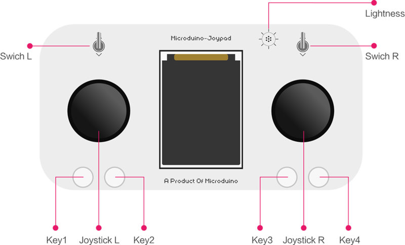
| + | ==Step-5 Description of the Keys== | ||
| + | [[File:Joypadbuttomreadme.png|center|800px]] | ||
| + | |||
| + | |||
| + | *Two rockers:Joystick L、Joystick R | ||
| + | *Two dial switches:Switch L、Switch R | ||
| + | *Four keys:Key1、Key2、Key3、Key4 | ||
| + | *one light sensor:Lightness | ||
| + | |||
| + | ==Step-6 Channel/Operating Instruction== | ||
| + | *Joystick L controls YAW[3] and THROT[4] channel,and Joystick R controls ROLL[1] and PITCH[2] channel. | ||
| + | *Key1, Key2, Key3, and Key4 are respectively corresponding with AUX1[5], AUX2[6], AUX3[7], and AUX4[8] channel. | ||
| + | *Switch L is responsible for locking the throttle. | ||
| + | *Switch R opens the small rudder model, and the rudder quantity will be smaller in this model. | ||
| + | ==Step-7 Menu Configuration Instruction== | ||
| + | |||
| + | ===Enter the Configuration Mode=== | ||
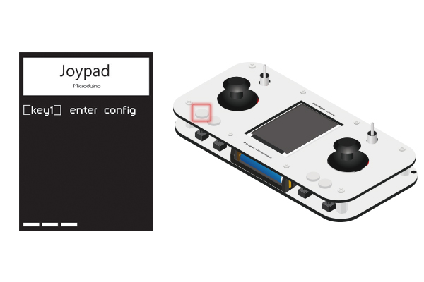
| + | *Within around the 4 seconds after opening Joypad, press down the Key1(the key on the bottom left), and it will enter the configuration (Config) mode. | ||
| + | **Note:You must enter before entering into the operation interface(around 2S). If not enter, restart to enter.''' | ||
| + | [[File:Step1进入设置.jpg|600px|center|]] | ||
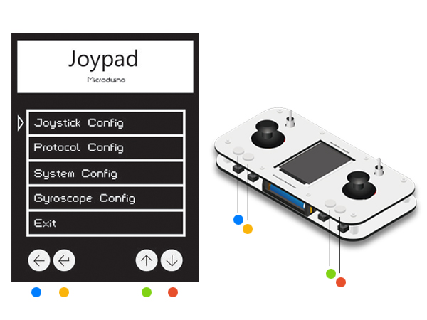
| + | * According to the color in the picture, they are Key1~Key4 from left to right. | ||
| + | [[File:Step1按键对应.jpg|600px|center|]] | ||
| + | *Press Key3 and Key4 to make the cursor move up and down. And Key1 is to return, and Key2 is to confirm. | ||
| + | |||
| + | ===Rocker Configuration=== | ||
| + | ====Rocker Calibration Setting==== | ||
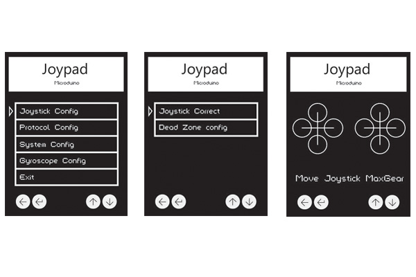
| + | *Choose “Joystick Config-Joystick Correct” to enter the rockers calibration mode. | ||
| + | **After entering, it will display the interface as shown in the third picture. And the initial state is two crosses. | ||
| + | **At this time, shake the two rockers to the top, the bottom, the most right, and the most left, four limitation state. | ||
| + | ***(The recommended operating mode:Shake the rockers in a circle.) | ||
| + | **After shaking, you will see circles appears in the four directions of the cross, and when the circle expands to the largest state, the position where it is is the limitation position. | ||
| + | [[File:Step2摇杆校准.jpg|600px|center|]] | ||
| + | ====Rocker Dead Zone Setting==== | ||
| + | *Choose “Joystick Config-Dead Zone config” to set the dead zone of the rockers. | ||
| + | **The bigger the values of the rockers you set, the less sensitive the rockers are. | ||
| + | |||
| + | ===Communication Protocol Configuration=== | ||
| + | ====Communication Model==== | ||
| + | *Choose “Protocol Config-mode” to enter the communication protocol configuration. | ||
| + | **The “Quadro.” is on behalf of quadrotor model in it, and “nRF24.” is on behalf of nRF model. | ||
| + | ====Quadrotor Model Channel Configuration==== | ||
| + | *Choose “Protocol Config-Quadrotor Channel” to set the communication channel of the quadrotor. | ||
| + | ====NRF Mode Channel Configuration==== | ||
| + | *Choose “Protocol Config-nRF24 Channel” to set the communication channel of nRF . | ||
| + | ===System Configuration=== | ||
| + | ====The Themes of the Screen Configuration==== | ||
| + | *Choose “System Config-TFT Theme” to switch the themes of the screen. | ||
| + | ====The Screen Flipping Configuration==== | ||
| + | *Choose “System Config-TFT Rotation” to flip the angle of the screen. | ||
| + | ====MCU Reference Voltage Configuration==== | ||
| + | *Choose “System Config-MCU Voltag” to configure the reference voltage of MCU. | ||
| + | ===Body Feeling Configuration=== | ||
| + | *Choose “Cyroscope Config” to configure the switch of the body feeling mode (needing [[Microduino-Motion]] to support) | ||
| + | |||
| + | ===End Configuration Mode=== | ||
| + | *Choose “Exit” to end the configuration mode. | ||
| + | |||
| + | ==FAQ== | ||
| + | *Q:'''Does Joypad support AAA battery?''' | ||
| + | **A:Yes, it does. And two pieces are needed, but the AAA battery is not recommended. | ||
| + | |||
| + | *Q:'''Why does Joypad not recommend to use AAA battery?''' | ||
| + | **A:The battery protection and the low electric quantity indicator of Joypad are designed for 3.7V lithium battery, and the voltage of the two AAA batteries will quickly trigger the protection circuit to cause the false scent of no electricity. | ||
| + | *Q:'''Which battery is recommended for Joypad?''' | ||
| + | **A:Single or two 10440 3.7V lithium batteries. | ||
| + | |||
| + | *Q:'''Which core module should I use to control the quadrotor remotely?''' | ||
| + | **A:CoreRF. CoreRF brings its own communication function, so other communication modules are needn’t. | ||
Latest revision as of 02:06, 10 June 2016
| Language: | English • 中文 |
|---|
Contents
Introduction & Overview
Background
Bill of Modules
Modules Selection
Bill of Material
Step-1 ProgrammingDownload the Source CodeAt first download the program from the following address [Joypad_RC] Stack Modules
Configure the Environment
Program Download
Step-2 Reference Voltage
Step-3 Battery poweredSpecifications of the Supported Battery
Active the Power Management Circuit
Electric Quantity Reminding and Charging(Limited to the 10440 Lithium Battery)
Step-4 Assembly
Step-5 Description of the Keys
Step-6 Channel/Operating Instruction
Step-7 Menu Configuration InstructionEnter the Configuration Mode
Rocker ConfigurationRocker Calibration Setting
Rocker Dead Zone Setting
Communication Protocol ConfigurationCommunication Model
Quadrotor Model Channel Configuration
NRF Mode Channel Configuration
System ConfigurationThe Themes of the Screen Configuration
The Screen Flipping Configuration
MCU Reference Voltage Configuration
Body Feeling Configuration
End Configuration Mode
FAQ
|
