Difference between revisions of "Microduino-Module RTC"
From Microduino Wiki
(→Spec) |
(→Pictures) |
||
| Line 44: | Line 44: | ||
==Pictures== | ==Pictures== | ||
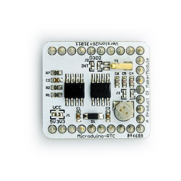
| − | [[file:rtc- | + | [[file:rtc-t.jpg|thumb|600px|center|Front]] |
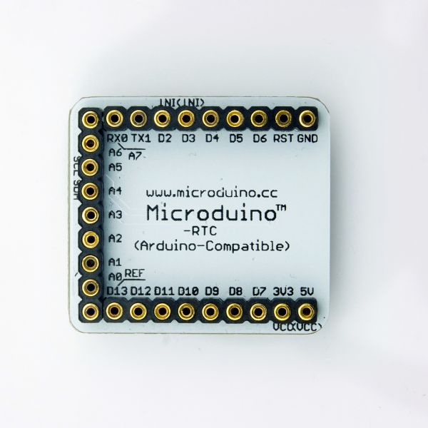
| − | [[file:rtc- | + | [[file:rtc-B.jpg|thumb|600px|center|Back]] |
[[File:RTC.png|thumb|600px|center|On board devices and Pin Map]] | [[File:RTC.png|thumb|600px|center|On board devices and Pin Map]] | ||
|- | |- | ||
|} | |} | ||
Revision as of 15:55, 22 January 2014
|
Microduino-RTC Module is a Real Time Clock module based on NXP CMOS PCF8563. RTC module uses TWI/I2C interface for communication. Data can be backed up with the addtional AT24c32 EEPROM. With an onboard capacitor, RTC module keeps time for serveral minutes after power disconnected. PCF8563 uses external crystal, and can provide timer intterupt tigger.
|
Buy |
History
|
SpecEagle PCB Download |
Main devices |
Arduino libraryPcf8563 Arduino Library【ArduinoPlayground 】【 Download】 |
PicturesFile:RTC.png On board devices and Pin Map |


