Difference between revisions of "Microduino-Shield Encoder"
From Microduino Wiki
(Created page with "{{Language|Microduino-Encoder}} {| style="width: 800px;" |- | 400px|thumb|right|Microduino- Encoder Microduino-Encoder is application...") |
(→Application) |
||
| (4 intermediate revisions by 3 users not shown) | |||
| Line 8: | Line 8: | ||
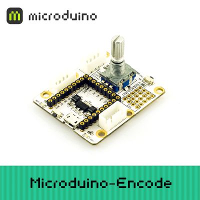
[[File: Microduino-Encoder-rect.jpg|400px|thumb|right|Microduino- Encoder]] | [[File: Microduino-Encoder-rect.jpg|400px|thumb|right|Microduino- Encoder]] | ||
| − | Microduino-Encoder is application board based rotary encoder control. | + | Microduino-Encoder is an application board based on rotary encoder control. |
| Line 27: | Line 27: | ||
==Specification== | ==Specification== | ||
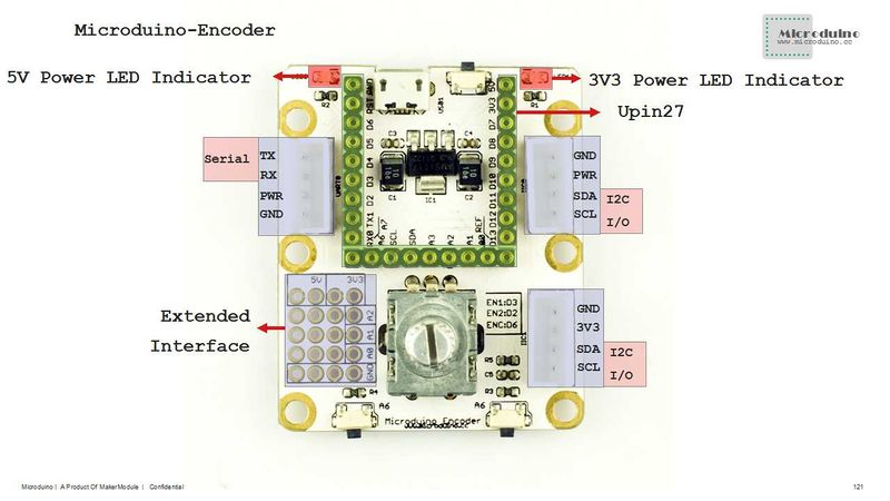
*Electrical specification | *Electrical specification | ||
| − | **MicroUSB power supply | + | **MicroUSB power supply. |
| − | **3V3 stabilivolt | + | **3V3 stabilivolt. |
| − | **PWR can select different voltage | + | **PWR can select different voltage values (5v or 3.3v) through jumpers. |
| − | **Onboard power source(5v and 3.3v) indicator | + | **Onboard power source(5v and 3.3v) indicator. |
*Extension | *Extension | ||
| − | **Onboard reset key | + | **Onboard reset key. |
| − | **OLED fixation base board | + | **OLED fixation base board. |
| − | **Serial RX0 and TX0 interface | + | **Serial RX0 and TX0 interface. |
| − | **Two IIC interfaces | + | **Two IIC interfaces. |
| − | **Two analog keys connected to A6 | + | **Two analog keys connected to A6. |
**There are bonding pads of analog serial port(A0,A1 and A2) and GND on the base board.(5v and 3.3v): | **There are bonding pads of analog serial port(A0,A1 and A2) and GND on the base board.(5v and 3.3v): | ||
| Line 52: | Line 52: | ||
*You can download Microduino test programs to have a simple test of its function: | *You can download Microduino test programs to have a simple test of its function: | ||
| − | [https://github.com/Microduino/Microduino_Tutorials/commit/da150a429c15c78262f9fd26a6d5e8ed827321e5 | + | [https://github.com/Microduino/Microduino_Tutorials/commit/da150a429c15c78262f9fd26a6d5e8ed827321e5 Rotary Encoder Test] |
| − | *All Hardware: Microduino USBTTL, Microduino-Core and Microduino- | + | *All Hardware: Microduino USBTTL, Microduino-Core and Microduino- Encoder; |
*All Software: Microduino test program(Arduino terminal) and Arduino IDE(Version 1.0 or higher); | *All Software: Microduino test program(Arduino terminal) and Arduino IDE(Version 1.0 or higher); | ||
*Open Microduino test program with IDE, choose Microduino-Core(Atmega328P@16M,5V) as the board and then download; | *Open Microduino test program with IDE, choose Microduino-Core(Atmega328P@16M,5V) as the board and then download; | ||
| Line 59: | Line 59: | ||
**Data keeps increasing when rotating right; | **Data keeps increasing when rotating right; | ||
**Data keeps decreasing when rotating left; | **Data keeps decreasing when rotating left; | ||
| − | **Press down the encoder and the data clears; | + | **Press down the encoder and the data clears; |
==Purchase== | ==Purchase== | ||
Latest revision as of 10:39, 24 August 2016
| Language: | English • 中文 |
|---|
|
Microduino-Encoder is an application board based on rotary encoder control.
Contents[hide]Feature
Specification
Document
DevelopmentIt can has a fast connection and extension with encoder and other Microduino modules to achieve different function. Application
PurchaseHistoryPictureFrontFile:Microduino-Encoder-F.JPG Microduino-Encoder Front BackFile:Microduino-Encoder-b.JPG Microduino-Encoder Back Video |


