Difference between revisions of "Microduino-Shield Robot"
From Microduino Wiki
m (Fengfeng moved page Microduino-Robot to Microduino-Shield Robot) |
|||
| (2 intermediate revisions by one other user not shown) | |||
| Line 1: | Line 1: | ||
| − | {{Language|Microduino-Robot | + | {{Language|Microduino-Robot}} |
{| style="width: 800px;" | {| style="width: 800px;" | ||
| − | + | |- | |
| + | | | ||
[[File: Microduino-Robot-rect.jpg|400px|thumb|right|Microduino- Robot]] | [[File: Microduino-Robot-rect.jpg|400px|thumb|right|Microduino- Robot]] | ||
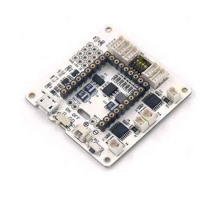
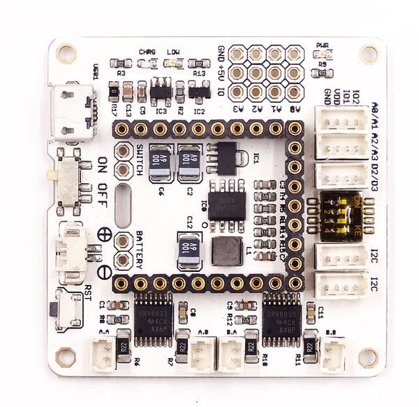
| + | Microduino-Robot shield, as a DC motor control board, can control 4 DC motors together with [[Microduino-Core]] and [[Microduino-Core+]]. And at the same time with sensor interfaces onboard, the users can connect it with varieties of sensors to achieve more functions. | ||
| − | + | The sensor / trinket connector are 4 pin, 1.25mm pitch JST connectors. | |
| − | |||
| − | |||
| + | The motor connector are 2 pin, 1.25mm pitch JST connectors. | ||
| − | == | + | ==Features== |
| − | * | + | *With lithium battery charging and discharging management, including charging, boosting(5V) and stabilivolt (3.3V) functions. |
| − | * | + | *With four motor driving interfaces, which makes it can drive four DC motor. |
| − | + | *With abundant sensor interfaces, which makes it can be easily extended. | |
| − | *Upin27 | + | *With Upin27 baseboard, which makes it can be connected with more Microduino modules. |
| − | * | + | *With small size, 46.99mm*40.64mm |
==Specification== | ==Specification== | ||
| − | * | + | *Electric |
| − | **5V | + | **5V boosting: Adopt G5177 rectifier booster chip, working voltage 3.0V~5V, and the output current 800mA |
| − | **3.3V stabilivolt: AMS1117 | + | **3.3V stabilivolt: AMS1117 stabilivolt plan, and the maximum output current can achieve 600mA. |
| − | ** | + | **Charging management: LTC4054 power management solution, and MicroUSB charging interface. |
| − | ** | + | **With battery interface and power switch onboard. |
| − | *Motor | + | **The battery interface and the power switch can be led out, which makes it easy to be controlled. |
| − | ** | + | *Motor driving |
| − | ** | + | **Adopt 2 DRV8833two-channel motor driver, and the driving power supply is battery, and each motor can continually provide RMS driving current up to 400mA. And they support the peak current up to 450mA. |
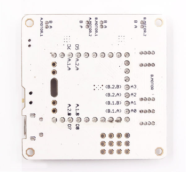
| − | * | + | **A driver pins: D6, D8, D5, D7 |
| − | + | **B driver pins: A0, A1, A2, A3 | |
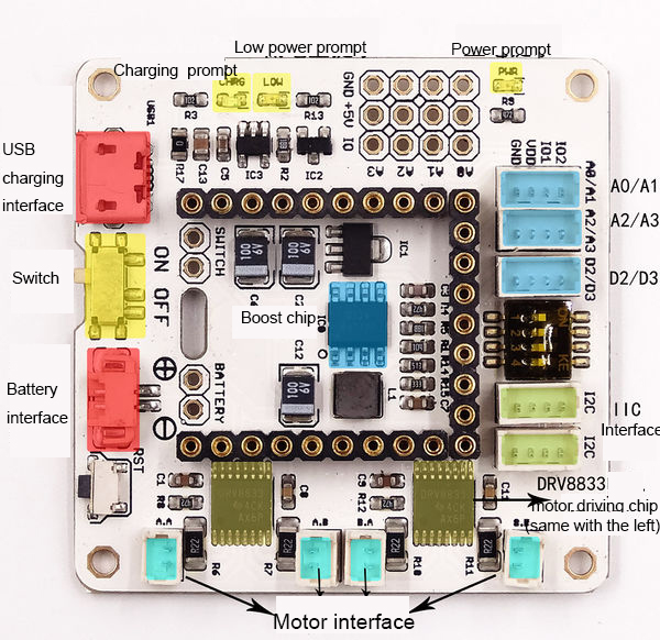
| − | * | + | ***'''The position from the head to the foot of the toggle switch as shown in the following picture is corresponding to the motor driving pin A0, A1, A2, A3''' |
| − | [[file: | + | ***'''Turn the corresponding toggle switch to ON, and this motor can be used to drive pins''' |
| − | + | *With 5 sensor interfaces onboard | |
| + | *With reset button onboard | ||
| + | [[file:ROBOTSHIELtips.jpg|thumb|600px|center]] | ||
==Document== | ==Document== | ||
| − | * | + | *Chip: '''[[File: DRV8833datasheet.pdf]]''' |
| + | *Microduino motor control library functions: [https://github.com/Microduino/Microduino-IDE-Support/tree/master/arduino-ide-Support/%5B1.6.x%5D-hardware%28library%29/hardware/Microduino/avr/libraries/_04_Microduino_Motor Microduino_Motor] | ||
| + | |||
==Development== | ==Development== | ||
| − | *For DC motor | + | |
| − | + | ===DC Motor Wiring=== | |
| + | Connect a DC motor to(A.MOTOR.1), and the other to (A.MOTOR.2); | ||
| + | Or one to (B.MOTOR.1), and the other to (B.MOTOR.2); | ||
| + | |||
| + | ===DC Motor Control Mode=== | ||
| + | *A driver | ||
| + | {|class="wikitable" | ||
| + | ! rowspan="1" |D6||D8||D5||D7||A.MOTOR.1.A||A.MOTOR.1.B||A.MOTOR.2.A||A.MOTOR.2.B||Function | ||
| + | |- | ||
| + | |0||0||0||0||Off||Off||Off||Off||Close | ||
| + | |- | ||
| + | |1||0||1||0||High||Low||High||Low||Forward | ||
| + | |- | ||
| + | |0||1||0||1||Low||High||Low||High||Reverse | ||
| + | |- | ||
| + | |1||1||1||1||Low||Low||Low||Low||Braking | ||
| + | |} | ||
| + | |||
| + | *B driver | ||
| + | {|class="wikitable" | ||
| + | ! rowspan="1" |A0||A1||A2||A3||B.MOTOR.1.A||B.MOTOR.1.B||B.MOTOR.2.A||B.MOTOR.2.B||Function | ||
| + | |- | ||
| + | |0||0||0||0||Off||Off||Off||Off||Close | ||
| + | |- | ||
| + | |1||0||1||0||High||Low||High||Low||Forward | ||
| + | |- | ||
| + | |0||1||0||1||Low||High||Low||High||Reverse | ||
| + | |- | ||
| + | |1||1||1||1||Low||Low||Low||Low||Braking | ||
| + | |} | ||
| + | |||
| + | |||
| + | |||
| + | *For driving DC motor, refer to: [[Microduino-Motor]]: | ||
| + | Example: | ||
<source lang="cpp"> | <source lang="cpp"> | ||
//=========M.A=============// | //=========M.A=============// | ||
| − | int mic_left_A = | + | int mic_left_A = 6; |
| − | int mic_right_A = | + | int mic_right_A = 8; |
| − | int mic_head_A = | + | int mic_head_A = 5; |
| − | int mic_back_A = | + | int mic_back_A = 7; |
//=========M.B=============// | //=========M.B=============// | ||
/* | /* | ||
| − | int | + | int mic_left_A = A0; |
| − | int | + | int mic_right_A =A1; |
| − | int | + | int mic_head_A = A2; |
| − | int | + | int mic_back_A = A3; |
*/ | */ | ||
void setup() { | void setup() { | ||
| Line 107: | Line 146: | ||
} | } | ||
</source> | </source> | ||
| − | |||
| − | |||
| − | |||
| − | |||
| − | |||
| − | |||
| − | |||
| − | |||
| − | |||
| − | |||
| − | |||
| − | |||
| − | |||
| − | |||
| − | |||
| − | |||
| − | |||
| − | |||
| − | |||
| − | |||
| − | |||
| − | |||
| − | |||
| − | |||
| − | |||
| − | |||
| − | |||
| − | |||
| − | |||
| − | |||
| − | |||
| − | |||
| − | |||
| − | |||
| − | |||
| − | |||
| − | |||
| − | |||
| − | |||
| − | |||
| − | |||
| − | |||
| − | |||
| − | |||
| − | |||
| − | |||
| − | |||
| − | |||
| − | |||
| − | |||
| − | |||
| − | |||
| − | |||
| − | |||
| − | |||
| − | |||
| − | |||
| − | |||
| − | |||
| − | |||
| − | |||
| − | |||
==Application== | ==Application== | ||
| − | ==='''[[ | + | ==='''[[Open Source Electric Drive Cube Robot]]'''=== |
| − | |||
| − | |||
==Purchase== | ==Purchase== | ||
| Line 179: | Line 154: | ||
==History== | ==History== | ||
| − | == | + | ==Gallery== |
*Front | *Front | ||
| − | [[file:Microduino-Robot-F.JPG | + | [[file:Microduino-Robot-F.JPG|600px|center]] |
*Back | *Back | ||
| − | [[file:Microduino-Robot-b.JPG | + | [[file:Microduino-Robot-b.JPG|600px|center]] |
| + | |||
==Video== | ==Video== | ||
|} | |} | ||
Latest revision as of 20:12, 21 February 2017
| Language: | English • 中文 |
|---|
|
Microduino-Robot shield, as a DC motor control board, can control 4 DC motors together with Microduino-Core and Microduino-Core+. And at the same time with sensor interfaces onboard, the users can connect it with varieties of sensors to achieve more functions. The sensor / trinket connector are 4 pin, 1.25mm pitch JST connectors. The motor connector are 2 pin, 1.25mm pitch JST connectors. ContentsFeatures
Specification
Document
DevelopmentDC Motor WiringConnect a DC motor to(A.MOTOR.1), and the other to (A.MOTOR.2); Or one to (B.MOTOR.1), and the other to (B.MOTOR.2); DC Motor Control Mode
Example: //=========M.A=============//
int mic_left_A = 6;
int mic_right_A = 8;
int mic_head_A = 5;
int mic_back_A = 7;
//=========M.B=============//
/*
int mic_left_A = A0;
int mic_right_A =A1;
int mic_head_A = A2;
int mic_back_A = A3;
*/
void setup() {
pinMode(mic_left_A,OUTPUT);
pinMode(mic_right_A,OUTPUT);
pinMode(mic_head_A,OUTPUT);
pinMode(mic_back_A,OUTPUT);
}
void loop() {
head();
delay(1500);
back();
delay(1500);
left();
delay(1500);
right();
delay(1500);
}
void head()
{
digitalWrite(mic_left_A,LOW);
digitalWrite(mic_right_A,HIGH);
digitalWrite(mic_head_A,HIGH);
digitalWrite(mic_back_A,LOW);
}
void left()
{
digitalWrite(mic_left_A,HIGH);
digitalWrite(mic_right_A,LOW);
digitalWrite(mic_head_A,HIGH);
digitalWrite(mic_back_A,LOW );
}
void right()
{
digitalWrite(mic_left_A,LOW);
digitalWrite(mic_right_A,HIGH);
digitalWrite(mic_head_A,LOW);
digitalWrite(mic_back_A,HIGH);
}
void back()
{
digitalWrite(mic_left_A,HIGH);
digitalWrite(mic_right_A,LOW);
digitalWrite(mic_head_A,LOW);
digitalWrite(mic_back_A,HIGH);
}
void stoop()
{
digitalWrite(mic_left_A,LOW);
digitalWrite(mic_right_A,LOW);
digitalWrite(mic_head_A,LOW);
digitalWrite(mic_back_A,LOW);
}ApplicationOpen Source Electric Drive Cube RobotPurchaseHistoryGallery
Video |


