|
|
| (2 intermediate revisions by 2 users not shown) |
| Line 1: |
Line 1: |
| | {| style="width: 800px;" | | {| style="width: 800px;" |
| | | colspan="2" | | | | colspan="2" | |
| − |
| |
| − | |-
| |
| − | |
| |
| − | ==Wired Communication==
| |
| − | |-
| |
| − | |
| |
| − | '''[[Microduino-W5500]]'''
| |
| − | *Microduino Ethernet module
| |
| − | *Support hardware TCP/IP protocol
| |
| − | *Built-in 10BaseT/100BaseTX Ethernet PHY
| |
| − | *Communicate with Core/Core+ through spi interface
| |
| − | *UPin-27 standard interface
| |
| − |
| |
| − | |
| |
| − | [[File:Microduino-W5500-rect.jpg|200px|right]]
| |
| − | |-
| |
| − | |
| |
| − | |-
| |
| − | |
| |
| − | '''[[Microduino-ENC28J60]]'''
| |
| − | *Main chip: ENC28J60
| |
| − | *Microduino ethnet module
| |
| − | *IEEE 802.3 compitable ethernet controller
| |
| − | *integrate MAC and 10 BASE-T PHY, support POE
| |
| − | *use SPI communication protocol
| |
| − | *UPin-27: Microduino standard interface
| |
| − | |
| |
| − | [[File:Microduino-enc-rect.jpg|200px|right]]
| |
| − | |-
| |
| − | |
| |
| − | '''[[Microduino-RJ45]]'''
| |
| − | *Main chip: ENC28J60
| |
| − | *Microduino ethnet module
| |
| − | *IEEE 802.3 compitable ethernet controller
| |
| − | *integrate MAC and 10 BASE-T PHY, support POE
| |
| − | *use SPI communication protocol
| |
| − | *UPin-27: Microduino standard interface
| |
| − | |
| |
| − | [[File:Microduino-rj45-rect.jpg|200px|right]]
| |
| − | |-
| |
| − | |
| |
| − |
| |
| − | '''[[Microduino-USBHOST]]'''
| |
| − | *Microduino USB communication module
| |
| − | *Support USB host controller and USB peripherals
| |
| − | *UPin-27 Microduino standard interface
| |
| − |
| |
| − | |[[File:Microduino-USBHOST-rect.jpg|200px|right]]
| |
| − | |-
| |
| − | |
| |
| − | ==Wireless Communication==
| |
| − | |-
| |
| − | |
| |
| − | '''[[Microduino-nRF24]]'''
| |
| − | *Microduino 2.4G wireless module
| |
| − | *use SPI communication protocol
| |
| − | *Arduino library support
| |
| − | |
| |
| − | [[file:Microduino-nRF-rect.jpg|200px|right]]
| |
| − | |-
| |
| − | |
| |
| − | '''[[Microduino-smartRF]]'''
| |
| − | *470/950 MHz ISM/SRD band ultra low power wireless communication module
| |
| − | *Use the SPI interface to communicate with Core/Core+ module
| |
| − | *Have corresponding networking library support, can carry on a simple network
| |
| − | *UPin-27 standard interface
| |
| − | |
| |
| − | [[file:Microduino smartRF-rect.jpg|200px|right]]
| |
| − | |-
| |
| − | |
| |
| − |
| |
| − | '''[[Microduino-NFC]]'''
| |
| − | *Two-way connection and identification of near-field communication module
| |
| − | *Use IIC interface to communicate with Core/Core+ module
| |
| − | *UPin-27 standard interface
| |
| − | |
| |
| − | [[file:Microduino-NFC-rect.jpg|200px|right]]
| |
| − | |-
| |
| − | |
| |
| − | '''[[Microduino-BT]]'''
| |
| − | *Microduino Shield BT, two versions are provided: BT2.1 and BT4.0
| |
| − | *support BT 2.1/4.0 protocol
| |
| − | *use hardware serial or software serial ports (optional)
| |
| − | *UPin-27: Microduino standard interface
| |
| − | |
| |
| − | [[File:Microduino-bt-rect.jpg|200px|right]]
| |
| − | |-
| |
| − | |
| |
| − | '''[[Microduino-Zigbee]]'''
| |
| − | *Microduino-Zigbee
| |
| − | *Adopt CC2530 chip
| |
| − | *Low-power, low-rate and low-cost two-way wireless communication
| |
| − | *UPin-27 standard interface
| |
| − |
| |
| − | |
| |
| − | [[File:Microduino-zigbee-rect.jpg|200px|right]]
| |
| − | |-
| |
| − | |
| |
| − | '''[[Microduino-WiFi]]'''
| |
| − | *Microduino WiFi Module
| |
| − | *Base on TI CC3000 IEEE 802.11b/g solution
| |
| − | *Use the SPI interface to communicate to Core module
| |
| − | *UPin-27: Microduino standard interface
| |
| − |
| |
| − | |[[File:Microduino-cc3000-rect.jpg|200px|right]]
| |
| − | |-
| |
| − | |
| |
| − | '''[[Microduino-GPRS/GSM]]'''
| |
| − | *Microduino GPRS/GSM module
| |
| − | *Send, Receive short message
| |
| − | *Access the network using SIM card
| |
| − |
| |
| − | |[[File:Microduino-GPRS-rect.jpg|200px|right]]
| |
| − | |-
| |
| − | |
| |
| | ==Battery Management== | | ==Battery Management== |
| | |- | | |- |
| | | | | | |
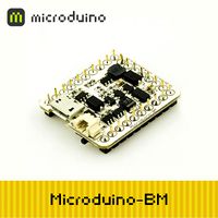
| − | '''[[Microduino-BM/zh]]''' | + | '''[[Microduino-BM]]''' |
| | *Microduino single-cell Li-ion battery charging and discharging management module | | *Microduino single-cell Li-ion battery charging and discharging management module |
| | *Support UPS; | | *Support UPS; |
| | *Highly integrate MicroUSB charging management, electrical quality detection, voltage output indication, 5V boost pressure and 3.3V LDO; | | *Highly integrate MicroUSB charging management, electrical quality detection, voltage output indication, 5V boost pressure and 3.3V LDO; |
| − |
| |
| | *UPin-27 standard interface | | *UPin-27 standard interface |
| | | | |
| Line 129: |
Line 13: |
| | [[File:Microduino-bm-rect.jpg|200px|right]] | | [[File:Microduino-bm-rect.jpg|200px|right]] |
| | |- | | |- |
| | + | |} |
| | + | |
| | + | {| style="width: 800px;" |
| | + | | colspan="2" | |
| | + | |
| | + | ==Position== |
| | | | | | |
| − |
| |
| − | == Position==
| |
| | |- | | |- |
| | | | | | |
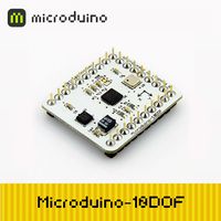
| − | '''[[Microduino-10DOF]]''' | + | '''[[Microduino-Motion]]''' |
| − | *Microduino 10 DOF sensor module | + | *Microduino-Motion (Microduino-10DOF)sensor module |
| | *MPU6050 + HMC5883L + BMP085 | | *MPU6050 + HMC5883L + BMP085 |
| | *use I2C protocol | | *use I2C protocol |
| Line 143: |
Line 31: |
| | [[File:Microduino-10dof-rect.jpg|200px|right]] | | [[File:Microduino-10dof-rect.jpg|200px|right]] |
| | |- | | |- |
| − | | | + | |} |
| − | '''[[Microduino-GPS]]'''
| + | |
| − | *Microduino GPS Module
| + | {| style="width: 800px;" |
| − | *Core modules using UBLOX NEO-6M
| + | | colspan="2" | |
| − | *Use serial to communicate with Core module
| |
| − | *UPin-27: Microduino standard interface
| |
| | | | |
| − | |[[File:Microduino-neo-6m-rect.jpg|200px|right]]
| |
| − | |-
| |
| − | |
| |
| | ==Multimedia/Clock/Storage== | | ==Multimedia/Clock/Storage== |
| | |- | | |- |
| Line 197: |
Line 80: |
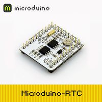
| | |[[File:Microduino-rtc-rect.jpg|200px|right]] | | |[[File:Microduino-rtc-rect.jpg|200px|right]] |
| | |- | | |- |
| − | | | + | |} |
| − | | |
| − | ==Display==
| |
| − | |-
| |
| − | |
| |
| − | '''[[Microduino-OLED]]'''
| |
| − | *Microduino OLED 12864 display module, 0.96'
| |
| − | *SSD1306 driver
| |
| − | *use I2C protocol
| |
| − | *supply voltage: 3.3V
| |
| | | | |
| − | |[[File:Microduino-oled-rect.jpg|200px|right]] | + | {| style="width: 800px;" |
| − | |-
| + | | colspan="2" | |
| − | |
| |
| − | '''[[Microduino-TFT]]'''
| |
| − | *Microduino-TFT display module
| |
| − | *ST7735 128*160 color display modules
| |
| − | *Adopt SPI interface and Core/Core+ communication
| |
| − | *3.3V power supply
| |
| − | | |
| − | |[[File:Microduino-tft-rect.jpg|200px|right]] | |
| − | |-
| |
| − | | | |
| | ==Motor Driver== | | ==Motor Driver== |
| | |- | | |- |
