Difference between revisions of "Key-press"
(→Debugging) |
|||
| (One intermediate revision by one other user not shown) | |||
| Line 28: | Line 28: | ||
To detect the key is long pressed or short pressed, which can be distinguished by checking the returned results in the serial monitor. | To detect the key is long pressed or short pressed, which can be distinguished by checking the returned results in the serial monitor. | ||
==Hardware Buildup== | ==Hardware Buildup== | ||
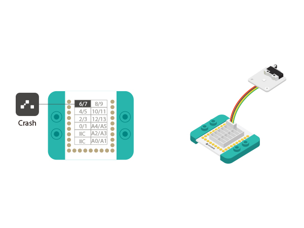
| − | *Setup | + | *Setup 1: Connect the interface on the back of the Crash to D6 port of the Hub, which is the control pin of the Crash and users can change that by yourselves. |
[[file:mCookie-Crash-sensor.JPG|600px|center]] | [[file:mCookie-Crash-sensor.JPG|600px|center]] | ||
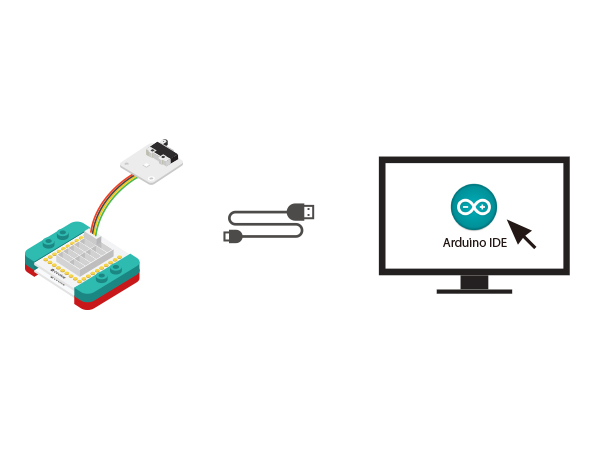
| − | *Setup | + | *Setup 2: Connect the CoreUSB, Hub and Crash together to the computer with a USB cable. |
[[file:mCookie-Crash-pc.JPG|600px|center]] | [[file:mCookie-Crash-pc.JPG|600px|center]] | ||
==Mixly Programming== | ==Mixly Programming== | ||
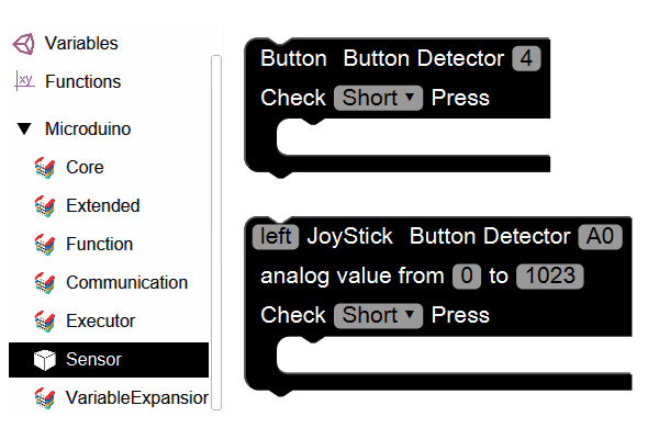
| − | * | + | *Step1: Open Mixly software and you'll find "Light Control" in "Executer" under the item of "Microduino". |
[[file:mixly-Crash.JPG|600px|center]] | [[file:mixly-Crash.JPG|600px|center]] | ||
| − | * | + | *Step2: Drag out the item of "Key". Since the hardware connection is connected to pin 6 while the pin 4 is the default one to be set after dragging out, you need to change "4' to 6". If you don't want to change, you can also connect the key to the pin 4 of the Hub. |
[[file:mixly-Crash-ready.JPG|600px|center]] | [[file:mixly-Crash-ready.JPG|600px|center]] | ||
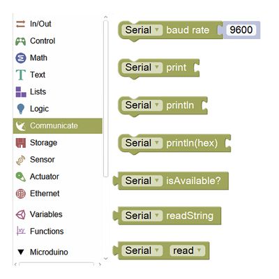
| − | * | + | *Step3: Since we use the serial monitor, we need to find "Serial communication" from "Communication" item. |
[[File:mixly_Serial.jpg|400px|center]] | [[File:mixly_Serial.jpg|400px|center]] | ||
| − | * | + | *Step4: Serial communication description. |
[[File:mixly_Serial_complian.jpg|600px|center]] | [[File:mixly_Serial_complian.jpg|600px|center]] | ||
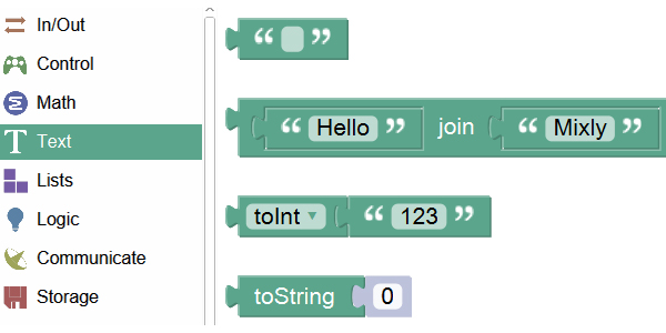
| − | * | + | *Step5: Fill in the content you want to print in the item of "Text", which must be English characters. |
[[File:mixly_text.jpg|600px|center]] | [[File:mixly_text.jpg|600px|center]] | ||
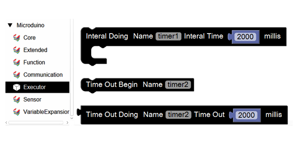
| − | * | + | *Step6: Since the long-press is always triggered, you can use system "Timer" to delay time, which can be found in "Executer". |
[[File:mixly_millis.jpg|600px|center]] | [[File:mixly_millis.jpg|600px|center]] | ||
| − | * | + | *Step7:System "Timer" description. |
[[File:mixly_millis_coplain.jpg|600px|center]] | [[File:mixly_millis_coplain.jpg|600px|center]] | ||
| − | * | + | *Step8:Overall code description. |
[[File:mixly_short_long.jpg|600px|center]] | [[File:mixly_short_long.jpg|600px|center]] | ||
==Debugging== | ==Debugging== | ||
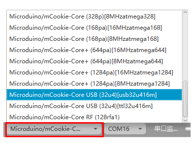
| − | + | Step1: Select the right board card(Core USB 32U4) and COM port(Recognized automatically by default). | |
[[File:mixly_board_COM.jpg|400px|center]] | [[File:mixly_board_COM.jpg|400px|center]] | ||
| − | + | Step2: Open the serial monitor. | |
[[File:mixly_COMXX.jpg|600px|center]] | [[File:mixly_COMXX.jpg|600px|center]] | ||
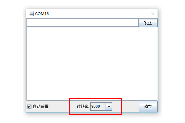
| − | + | Step3: Make sure the serial baud rate is the same with the pre-set one. | |
[[File:mixly_COMXX_ok.jpg|600px|center]] | [[File:mixly_COMXX_ok.jpg|600px|center]] | ||
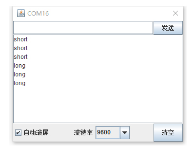
| − | + | Step4: Short press or long press the key and you'll see "short" or "long" pressed in the serial monitor every 1s. | |
[[File:mixly_Serial_shortlong.jpg|400px|center]] | [[File:mixly_Serial_shortlong.jpg|400px|center]] | ||
| Line 68: | Line 68: | ||
==Mixly Programming== | ==Mixly Programming== | ||
| − | * | + | *Step1: Open Mixly software and find the relevant Serial items in "Communication" since we need the serial monitor to observe results. |
[[File:mixly_Serial.jpg|400px|center]] | [[File:mixly_Serial.jpg|400px|center]] | ||
| − | * | + | *Step2: Since there're only two states, you can introduce Boolean variable to achieve that, which can be found in "Variable". |
[[File:mixly_boolean.jpg|600px|center]] | [[File:mixly_boolean.jpg|600px|center]] | ||
*"Variable" description. | *"Variable" description. | ||
[[File:mixly_boolean_explain.jpg|600px|center]] | [[File:mixly_boolean_explain.jpg|600px|center]] | ||
| − | * | + | *Step3: Drag out the item of "Key". Since the hardware connection is connected to pin 6 while the pin 4 is the default one to be set after dragging out, you need to change "4' to 6". |
| − | * | + | *Step4: Judge the status of the key. Make Boolean value as its own "No" value, and every time you press the key, the status of the Boolean value will turn over once and there is a loop between "True" and "False". Therefore, you can print "ON" or "OFF" by judging "True" or "False". |
| − | * | + | *Step5: Need to use logic parameter: False. Found it in the "Logic" item. |
[[File:mixly_boolean_no.jpg|600px|center]] | [[File:mixly_boolean_no.jpg|600px|center]] | ||
*"False" description. | *"False" description. | ||
[[File:mixly_no_explain.jpg|600px|center]] | [[File:mixly_no_explain.jpg|600px|center]] | ||
| − | * | + | *Step6: Next, we need to judge the "True" or "False" value of the Boolean variable. You can find condition statement in "Control". |
[[File:mixly_if.jpg|600px|center]] | [[File:mixly_if.jpg|600px|center]] | ||
*Condition judgment description. | *Condition judgment description. | ||
[[File:mixly_if_explain.jpg|600px|center]] | [[File:mixly_if_explain.jpg|600px|center]] | ||
| − | * | + | *Step7: Find out "Serial Communication" item and the "Text" item, make judgment according to Boolean variable, therefore, print out "ON" or "OFF". |
| − | * | + | *Step8: Overall code description. |
[[File:mixly_boolean_explain2.jpg|600px|center]] | [[File:mixly_boolean_explain2.jpg|600px|center]] | ||
==Debugging== | ==Debugging== | ||
| − | + | Step1: Select the right board card(Core USB 32U4) and COM port(Recognized automatically by default). | |
[[File:mixly_board_COM.jpg|400px|center]] | [[File:mixly_board_COM.jpg|400px|center]] | ||
| − | + | Step2: Open the serial monitor. | |
| − | [[File:mixly_COMXX.jpg| | + | [[File:mixly_COMXX.jpg|600px|center]] |
| − | + | Step3: Make sure the serial baud rate is the same with the pre-set one. | |
| − | [[File:mixly_COMXX_ok.jpg| | + | [[File:mixly_COMXX_ok.jpg|600px|center]] |
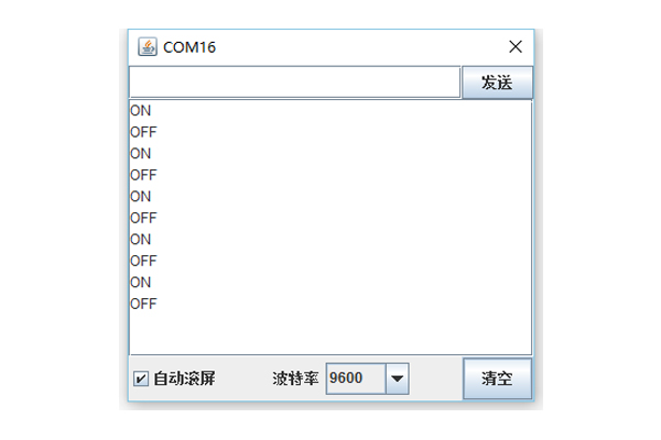
| − | + | Step4: Short press the key once and you'll see "ON' printed in the serial monitor. Press down again and you'll see "OFF" printed. | |
[[File:mixly_Serial_boolean.jpg|600px|center]] | [[File:mixly_Serial_boolean.jpg|600px|center]] | ||
| + | |||
==Extension== | ==Extension== | ||
By changing the serial port print to the colored lights, you can DIY a little desk lamp. | By changing the serial port print to the colored lights, you can DIY a little desk lamp. | ||
|} | |} | ||
Latest revision as of 09:44, 13 September 2016
ContentsFunction of the Module
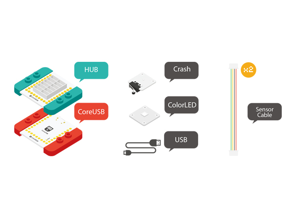
Equipment
Example 1: Long-press & Short-press FunctionOverviewTo detect the key is long pressed or short pressed, which can be distinguished by checking the returned results in the serial monitor. Hardware Buildup
Mixly Programming
DebuggingStep1: Select the right board card(Core USB 32U4) and COM port(Recognized automatically by default). Step2: Open the serial monitor. Step3: Make sure the serial baud rate is the same with the pre-set one. Step4: Short press or long press the key and you'll see "short" or "long" pressed in the serial monitor every 1s. Experiment 2: State Turnover FunctionOverviewEach time you press down a key, the status will turn over once. Like a desk lamp, when you press down, it turns on. And press one more time, it'll turn off. There're only two states. We can see the result through the serial monitor. Pressing down means "ON" (print "ON" in the serial monitor)and one more time, means "OFF"("OFF" printed in the serial monitor). Hardware Buildup
Mixly Programming
DebuggingStep1: Select the right board card(Core USB 32U4) and COM port(Recognized automatically by default). Step2: Open the serial monitor. Step3: Make sure the serial baud rate is the same with the pre-set one. Step4: Short press the key once and you'll see "ON' printed in the serial monitor. Press down again and you'll see "OFF" printed. ExtensionBy changing the serial port print to the colored lights, you can DIY a little desk lamp. |
