Difference between revisions of "MCookie-LED Matrix"
From Microduino Wiki
(Created page with "{| style="width: 800px;" |- | ==Outline== mCookie-LED Matrix module integrate 6 WS2812 LEDs, each of which has an IC control chip. Them are controlled by a single bus, and the...") |
(→Document) |
||
| (12 intermediate revisions by 2 users not shown) | |||
| Line 2: | Line 2: | ||
|- | |- | ||
| | | | ||
| + | [[File:MCookie-led-Matrix-rect.jpg|400px|thumb|right]] | ||
==Outline== | ==Outline== | ||
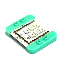
mCookie-LED Matrix module integrate 6 WS2812 LEDs, each of which has an IC control chip. Them are controlled by a single bus, and the lighting status of each of them is controlled by an I/O port, which can be used as a full-color module to provide light source. | mCookie-LED Matrix module integrate 6 WS2812 LEDs, each of which has an IC control chip. Them are controlled by a single bus, and the lighting status of each of them is controlled by an I/O port, which can be used as a full-color module to provide light source. | ||
==Features== | ==Features== | ||
| − | *Single bus control, only need one I/O port to control, and complete data receiving and | + | *Single bus control, only need one I/O port to control, and complete data receiving and decoding; |
| − | *Built-in IC control, serial cascade interfaces which can be cascaded | + | *Built-in IC control, serial cascade interfaces which can be cascaded controlled; |
| − | *The three primary color of each pixel can realize 256 level light display, and complete 16777216 colors whole true display, and the scanning frequency is no less then 400Hz/ | + | *The three primary color of each pixel can realize 256 level light display, and complete 16777216 colors whole true display, and the scanning frequency is no less then 400Hz/s; |
| − | *Built-in power on reset circuit and power down reset | + | *Built-in power on reset circuit and power down reset circuit. |
==Specification== | ==Specification== | ||
| − | *Electric specification | + | *Electric specification: |
| − | **Working | + | **Working voltage: 5V; |
| − | **Controlling light | + | **Controlling light source: WS2812*6. |
| − | *Technical parameters | + | *Technical parameters: |
| − | **WS2812 type | + | **WS2812 type; |
| − | **Gray of three primary | + | **Gray of three primary colors: adjustable 256 level; |
| − | **Size of | + | **Size of LED: 5mm*5mm; |
**The speed of data sending can reach 800Kbps. | **The speed of data sending can reach 800Kbps. | ||
| − | *Connection | + | *Connection: |
| − | **Direct adsorption on other modules | + | **Direct adsorption on other modules; |
| − | **Connect to '''A0''' | + | **Connect to pin '''A0''' by default. |
[[File: led-Matrix_steup1.jpg|600px|center]] | [[File: led-Matrix_steup1.jpg|600px|center]] | ||
[[File: led-Matrix_steup2.jpg|600px|center]] | [[File: led-Matrix_steup2.jpg|600px|center]] | ||
==Document== | ==Document== | ||
| − | [[File:ws2812.pdf]] | + | *LED Matrix uses the WS2812 color LED: [[File:ws2812.pdf]] |
| + | *Adafruit's Neopixel to control. Guide here: '''https://learn.adafruit.com/adafruit-neopixel-uberguide/arduino-library''' | ||
| + | |||
==Development== | ==Development== | ||
===Equipment=== | ===Equipment=== | ||
| Line 50: | Line 53: | ||
#include <Adafruit_NeoPixel.h> | #include <Adafruit_NeoPixel.h> | ||
| − | #define PIN A0 // | + | #define PIN A0 //Pin that the LEDs are connected to. LED Matrix is wired to pin A0. |
| − | #define PIN_NUM 6 //Number of | + | #define PIN_NUM 6 //Number of LEDs daisy chained, LED Matrix is 6 LEDs daisy chained. |
Adafruit_NeoPixel strip = Adafruit_NeoPixel(PIN_NUM, PIN, NEO_GRB + NEO_KHZ800); | Adafruit_NeoPixel strip = Adafruit_NeoPixel(PIN_NUM, PIN, NEO_GRB + NEO_KHZ800); | ||
| Line 90: | Line 93: | ||
===Program Description=== | ===Program Description=== | ||
| − | *Use | + | *Use "Adafruit_NeoPixel.h" library to drive lights; |
| − | * | + | *"#define PIN A0" defines the controlling LED pin, which can be transferred out through the Hub, and can be changed be the users; |
| − | * | + | *"#define PIN_NUM 6" defines the number of leds allowed to connect; |
| − | * | + | *"strip.setPixelColor(i, strip.Color(R, G, B));" function declaration: |
| − | ** | + | **i: Which light. '''Starting from 0 to be taken as the first light.''' |
| − | ** | + | **R: The red value(0-255); |
| − | ** | + | **G: The green value(0-255); |
| − | ** | + | **B: The blue value(0-255). |
| − | * | + | *"strip.show();" shows LED display. |
| − | |||
===Other Controlling Methods=== | ===Other Controlling Methods=== | ||
| − | *Reference | + | *Reference code: [https://github.com/wasdylb/mCookie/tree/master/module/LED_Matrix LED_Matrix] |
==Application== | ==Application== | ||
Latest revision as of 22:04, 29 March 2017
Contents[hide]OutlinemCookie-LED Matrix module integrate 6 WS2812 LEDs, each of which has an IC control chip. Them are controlled by a single bus, and the lighting status of each of them is controlled by an I/O port, which can be used as a full-color module to provide light source. Features
Specification
Document
DevelopmentEquipment
Preparation
Experiment 1:Light up the Lights
#include <Adafruit_NeoPixel.h>

#define PIN A0   //Pin that the LEDs are connected to. LED Matrix is wired to pin A0.
#define PIN_NUM 6 //Number of LEDs daisy chained, LED Matrix is 6 LEDs daisy chained.

Adafruit_NeoPixel strip = Adafruit_NeoPixel(PIN_NUM, PIN, NEO_GRB + NEO_KHZ800);

void setup() {
  strip.begin();
}

void loop() {
  strip.setPixelColor(0, strip.Color(255, 0, 0));//Red
  strip.show();
  delay(1000);
  strip.setPixelColor(1, strip.Color(0, 255, 0));//Green
  strip.show();
  delay(1000);
  strip.setPixelColor(2, strip.Color(0, 0, 255));//Blue
  strip.show();
  delay(1000);
  strip.setPixelColor(3, strip.Color(255, 255, 0));
  strip.show();
  delay(1000);
  strip.setPixelColor(4, strip.Color(0, 255, 255));
  strip.show();
  delay(1000);
  strip.setPixelColor(5, strip.Color(255, 0, 255));
  strip.show();
  delay(1000);
}
Program Description
Other Controlling Methods
Application
PurchaseHistoryGalleryVideo |


