Difference between revisions of "Microduino NRF communication-201KIT"
(Created page with "{| style="width: 800px;" |- | ==概述== *项目名称:Microduino nrf24通讯 *目的:通过microduino nrf24模块对led灯进行无线控制。结合按键控制led灯的...") |
|||
| (10 intermediate revisions by 4 users not shown) | |||
| Line 1: | Line 1: | ||
| + | {{Language|Microduino_nrf通讯-201KIT}} | ||
{| style="width: 800px;" | {| style="width: 800px;" | ||
|- | |- | ||
| | | | ||
| − | == | + | ==Outline== |
| − | * | + | *Project: Microduino nrf24 communication |
| − | * | + | *Objective: To have a wireless control of the LED light via Microduino-NRF24. |
| − | * | + | *Difficulty: Elementary |
| − | * | + | *Time-consuming: Half an hour |
| − | * | + | *Maker: Microduino Studio-YLB |
| − | == | + | ==Bill of Materials== |
| − | * | + | *Microduino equipment |
{|class="wikitable" | {|class="wikitable" | ||
|- | |- | ||
| − | | | + | |Module||Number||Function |
|- | |- | ||
| − | |Microduino-Core+||1|| | + | |Microduino-Core+/Microduino-Core||1||Used as a master machine to send the control signal |
|- | |- | ||
| − | |Microduino-Core||1|| | + | |Microduino-Core||1||Used as a slave machine to receive the control signal |
|- | |- | ||
| − | |Microduino-FT232R ||1|| | + | |Microduino-USBTTL(FT232R) ||1||For program download |
|- | |- | ||
| − | |Microduino-nRF24||2|| | + | |Microduino-nRF24||2||For wireless communication |
|} | |} | ||
| − | * | + | *Other equipment |
{|class="wikitable" | {|class="wikitable" | ||
|- | |- | ||
| − | | | + | |Button||1||For function selection |
|- | |- | ||
| − | | | + | |LED||1||For displaying communication status |
|- | |- | ||
| − | | | + | |bread board||1||For circuit buildup |
|- | |- | ||
| − | | | + | |Jumper||1||For circuit connection |
|} | |} | ||
| − | * | + | *Module |
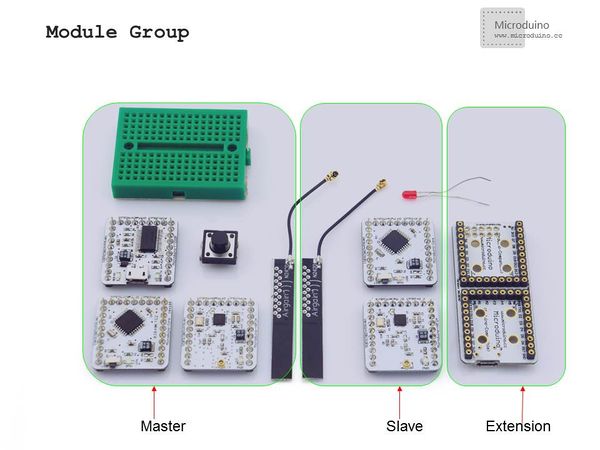
| − | + | For ease of debugging and lowering the height of the module combination, here we need an extension board Microduino-Duo-V1. | |
| − | |||
| − | + | [[File:module.jpg|600px|center|thumb|201KIT]] | |
| − | == | + | ==Document== |
| + | |||
| + | ==Debugging== | ||
|- | |- | ||
| | | | ||
| − | * | + | *Step 1: Set up the system |
|- | |- | ||
| | | | ||
| − | + | Prepare master module: | |
| − | Microduino-Core+ | + | Microduino-Core+, Microduino-FT232R, Microduino-nRF24, a button and a bread board |
|- | |- | ||
| | | | ||
| − | + | Prepare slave module: | |
| − | Microduino-Core | + | Microduino-Core, Microduino-NRF24,Microduino Duo-V and an LED |
|- | |- | ||
| | | | ||
| − | * | + | *Step 2: Set up the button |
| − | + | Button connection: Adopt internal pull up. (You need to define it in program.) | |
| − | [[File:201KIT-button.jpg|600px|center|thumb|201KIT- | + | [[File:201KIT-button.jpg|600px|center|thumb|201KIT-button]] |
|- | |- | ||
| | | | ||
| − | + | The whole system picture: | |
| − | [[File:201KIT- | + | [[File:201KIT-system.jpg|600px|center|thumb|201KIT]] |
|- | |- | ||
| | | | ||
| − | * | + | *Step 3: Download the example program |
| − | + | Download the program: | |
|- | |- | ||
| | | | ||
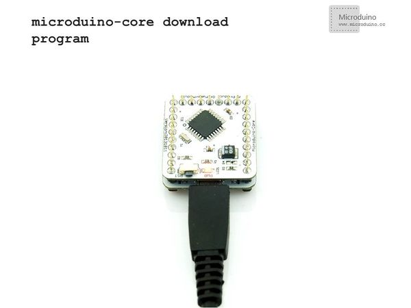
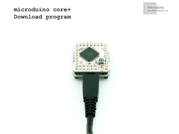
| − | + | Choose "Microduino Core +(Atmega644P@16M,5V)" as the board of the master machine and "Microduino Core (Atmega328P@16M,5V)" as that of the slave machine, then download directly. | |
| + | |||
[[File:download-core.jpg|600px|center|thumb|download-core]] | [[File:download-core.jpg|600px|center|thumb|download-core]] | ||
[[File:download-core+.jpg|600px|center|thumb|download-core+]] | [[File:download-core+.jpg|600px|center|thumb|download-core+]] | ||
| − | == | + | ==Result== |
| − | + | Just download the program to the core board and you can control the LED on the slave machine through the button on the master machine. | |
| − | == | + | ==Note== |
| − | * | + | *The sending and receiving parameters of Microduino-NRF24's communication function should be matched. |
| − | * | + | *The button adopts internal pull up, needed to be defined in program. |
|} | |} | ||
Latest revision as of 05:44, 30 September 2016
| Language: | English • 中文 |
|---|
Outline
Bill of Materials
For ease of debugging and lowering the height of the module combination, here we need an extension board Microduino-Duo-V1. DocumentDebugging | |||||||||||||||||||||||||||
| |||||||||||||||||||||||||||
|
Prepare master module: Microduino-Core+, Microduino-FT232R, Microduino-nRF24, a button and a bread board | |||||||||||||||||||||||||||
|
Prepare slave module: Microduino-Core, Microduino-NRF24,Microduino Duo-V and an LED | |||||||||||||||||||||||||||
Button connection: Adopt internal pull up. (You need to define it in program.) | |||||||||||||||||||||||||||
|
The whole system picture: | |||||||||||||||||||||||||||
Download the program: | |||||||||||||||||||||||||||
|
Choose "Microduino Core +(Atmega644P@16M,5V)" as the board of the master machine and "Microduino Core (Atmega328P@16M,5V)" as that of the slave machine, then download directly. ResultJust download the program to the core board and you can control the LED on the slave machine through the button on the master machine. Note
|


