|
|
| (182 intermediate revisions by 22 users not shown) |
| Line 1: |
Line 1: |
| − | {{Language|Main Page}}
| + | {| class="titlebox" width="100%" style="border:2px solid #000000; -moz-border-radius:5px 5px 5px 5px; -webkit-border-radius:5px 5px 5px 5px;" cellspacing=0 cellpadding=0 |
| − | {| class="titlebox" width="800px" style="border:2px solid #000000; -moz-border-radius:5px 5px 5px 5px; -webkit-border-radius:5px 5px 5px 5px;" cellspacing=0 cellpadding=0 | + | ! style="background:#000000; border-radius:2px; padding:5px; color:#ffffff;" | <div style="font-size:180%;text-align:center;">Microduino Wiki</div> |
| − | ! style="background:#000000; border-radius:2px; padding:5px; color:#ffffff;" | <div style="font-size:180%;text-align:center;">Welcome to Microduino Wiki</div> | |
| − | |-
| |
| − | |
| |
| − | {|
| |
| − | |-
| |
| − | |[[file:Headline.png|800px|left]]
| |
| − | |}
| |
| − | |-
| |
| − | |
| |
| − | {|
| |
| − | |-
| |
| − | | Small size, full energy! Microduino series is 100% Arduino compitable open source hardware, compatible with Arduino IDE development environment and existing Arduino programs.
| |
| − | |-
| |
| − | | All Microduino boards adapt uniformed U-shape 27-pin standard interface (UPin-27), Microduino series can be easily stacked together through UPin-27, it is delivered ready to plug in. Microduino board size is as small as a quarter (25.40mm X 27.94mm / 1.0inch X 1.1inch), with tiny shape, Microduino series dramatically decreases the size and cost of design prototype, remarkable improves usability and flexibility of Arduino-compitable boards, as well as user experience.
| |
| − | |-
| |
| − | | Microduino series is typically applied in idea realization, prototype development and low volume production.
| |
| − | |-
| |
| − | |
| |
| − | Version en español:
| |
| − | |-
| |
| − | | Tamaño pequeño, Energia total! La serie Microduino es 100% compatible con hardware de codigo abierto Arduino, compatible con el entorno de desarrollo IDE Arduino y programas de Arduino existentes.
| |
| − | |-
| |
| − | | Todas las placas Microduino se adaptan uniformemente con la interface estandard U-shape de 27-pin (UPin-27), la serie Microduino puede facilmente apilarse conjuntamente a travez de UPin-27, se suministra lista para su conexion. El tamaño de la placa Microduino es tan pequeño como una moneda de 25 centavos (25.40 mm X 27.94 mm / 1.0 pulgadas X 1.1 pulgadas), con forma pequeña, La Series Microduino disminuye drásticamente el tamaño y el costo del diseño de prototipos, notable mejora de la facilidad de uso y flexibilidad con placas Arduino-compitable, así como la experiencia del usuario.
| |
| − | |-
| |
| − | | La Series Microduino es utiliza normalmente en realización de conceptos, desarrollo de prototipos y producción de bajo volumen.
| |
| − | |}
| |
| | |} | | |} |
| | | | |
| − | {| style="width: 800px; margin-top: 10px;"
| |
| − | |- style="color: #f00; font-size: 16px;"
| |
| − | |'''CAUTION:
| |
| − | |- style="color: #f00;"
| |
| − | |'''Be noticed that Microduino studio NEVER authorize any other one to sell any Microdino product. '''
| |
| − | |-
| |
| − | |- style="height:10px;"
| |
| − | |- style="color: #f00;"
| |
| − | |'''Les notificamos que Microduino studio NUNCA authorizo a nadie a vender cualquier producto Microdino. '''
| |
| − | |}
| |
| | | | |
| − | {|style="height:10px;" | + | {| class="titlebox" width="300px" style="border:2px solid #000000; -moz-border-radius:10px 10px 10px 10px; -webkit-border-radius:10px 10px 10px 10px;" cellspacing=0 cellpadding=0 |
| − | |-
| + | ! style="background:#FFFFFF; border-radius:10px; padding:10px; color:#000000;" | <div style="font-size:140%;text-align:center;">Software Setup</div> |
| − | |Homepage: http://www.Microduino.cc/
| |
| − | |-
| |
| − | |Facebook: https://www.Facebook.com/Microduino/
| |
| − | |-
| |
| − | |Twitter: http://www.Twitter.com/Microduino/
| |
| − | |-style="height:15px;" | |
| − | |
| |
| − | Fritzing :'''[[File:Microduino-Frzting.zip]]'''
| |
| − | | |
| − | Downlaod Microduino IDE package:【[[Media:Microduino-hardware.zip]]】
| |
| − | |-
| |
| | |} | | |} |
| | + | {{Clickable_headed_image_table_box_small|header=Microduino IDE|link=Software Setup: Arduino|image=File:Arduino_Logo.png|image_size=140px|table_width=175px|table_height=150px}} |
| | + | {{Clickable_headed_image_table_box_small|header=mDesigner|link=Software Setup: mDesigner|image=File:mDesigner Logo.png|image_size=140px|table_width=175px|table_height=150px}} |
| | + | {{Clickable_headed_image_table_box_clear}} |
| | | | |
| − | {| style="width: 800px;" | + | {| class="titlebox" width="300px" style="border:2px solid #000000; -moz-border-radius:10px 10px 10px 10px; -webkit-border-radius:10px 10px 10px 10px;" cellspacing=0 cellpadding=0 |
| − | | colspan="2" |
| + | ! style="background:#FFFFFF; border-radius:10px; padding:10px; color:#000000;" | <div style="font-size:140%;text-align:center;">Guides</div> |
| − | ==Microduino Core Modules (Arduino Compitable)== | |
| − | |-
| |
| − | |
| |
| − | '''[[Microduino-Core]]'''
| |
| − | *Core board of Microduino series
| |
| − | *Main chip: ATmega328P/ATmega168PA
| |
| − | *Compatible with Arduino Uno, the same hardware architect as Uno.
| |
| − | *UPin-27: Microduino standard interface
| |
| − | |[[file:Microduino-core-rect.jpg|200px|right]]
| |
| − | |-
| |
| − | |
| |
| − | '''[[Microduino-Core+]]''' (Performance Edition)
| |
| − | *Core board of Microduino series
| |
| − | *Main chip: ATmega644PA/ATmega1284P
| |
| − | *As powerful as Arduino Mega2560
| |
| − | *2 hardware serial ports, 10 more digital I/O
| |
| − | *UPin-27: Microduino standard interface
| |
| − | |[[file:Microduino-core+-rect.jpg|200px|right]]
| |
| − | | |
| − | |-
| |
| − | |
| |
| − | '''[[Microduino-Core32U4]]'''(Performance Edition)
| |
| − | *Core board of Microduino series
| |
| − | *Compatible with Arduino Uno
| |
| − | *Contain Microcontroller and USB
| |
| − | *UPin-27: Microduino standard interface
| |
| − | |[[File:Microduino-core32U4-rect.jpg|200px|right]] | |
| − | |-
| |
| − | |
| |
| − | '''[[Microduino-FT232R]]'''
| |
| − | *Microduino USB2TTL module, connecting PC with Microduino, uploading program to Core/Core+.
| |
| − | *Main chip: FT232RL
| |
| − | *UPin-27: Microduino standard interface
| |
| − | |[[file:Microduino-ft232-rect.jpg|200px|right]]
| |
| − | | |
| | |} | | |} |
| | | | |
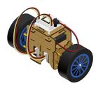
| | + | {{Clickable_headed_image_table_box_small|header=Itty Bitty Buggy|link=Itty_Bitty_Buggy_Tutorials|image=File:IBB.png|image_size=140px|table_width=175px|table_height=150px}} |
| | + | {{Clickable_headed_image_table_box_small|header=Itty Bitty City|link=Itty_Bitty_City|image=File:IBC.png|image_size=140px|table_width=175px|table_height=150px}} |
| | + | {{Clickable_headed_image_table_box_clear}} |
| | + | {{Clickable_headed_image_table_box_small|header=mCookie 101 Basic|link=MCookie_Basic_Kit_Tutorials|image=File:mCookie_Basic_Kit.png|image_size=140px|table_width=175px|table_height=150px}} |
| | + | {{Clickable_headed_image_table_box_small|header=mCookie 201 Advanced|link=MCookie_Advanced_Kit_Tutorials|image=File:mCookie_Advanced_Kit.png|image_size=140px|table_width=175px|table_height=150px}} |
| | + | {{Clickable_headed_image_table_box_small|header=mCookie 301 Expert|link=MCookie_Expert_Kit_Tutorials|image=File:mCookie_Expert_Kit.png|image_size=140px|table_width=175px|table_height=150px}} |
| | + | {{Clickable_headed_image_table_box_clear}} |
| | + | {{Clickable_headed_image_table_box_small|header=mCookie 102 Basic|link=MCookie_102_Basic_Kit_Tutorials|image=File:mCookie_102_Basic_Kit.png|image_size=140px|table_width=175px|table_height=150px}} |
| | + | {{Clickable_headed_image_table_box_small|header=mCookie 202 Advanced|link=MCookie_202_Advanced_Kit_Tutorials|image=File:mCookie_202_Advanced_Kit.png|image_size=140px|table_width=175px|table_height=150px}} |
| | + | {{Clickable_headed_image_table_box_small|header=mCookie 302 Expert|link=MCookie_302_Expert_Kit_Tutorials|image=File:mCookie_302_Expert_Kit.png|image_size=140px|table_width=175px|table_height=150px}} |
| | + | {{Clickable_headed_image_table_box_clear}} |
| | + | {{Clickable_headed_image_table_box_small|header=Cube Car|link=Cube_Robot|image=File:CubeCar.jpg|image_size=130px|table_width=175px|table_height=150px}} |
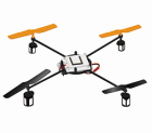
| | + | {{Clickable_headed_image_table_box_small|header=Quadcopter|link=Quadcopter_Kit:_Quickstart_Guide|image=File:Quadcopter_Small.png|image_size=140px|table_width=175px|table_height=150px}} |
| | + | {{Clickable_headed_image_table_box_small|header=Self-Balancing Robot|link=Open_Source_Self-balance_Robot_System|image=File:Balancestep7-1.jpg|image_size=140px|table_width=175px|table_height=150px}} |
| | + | {{Clickable_headed_image_table_box_small|header=Weather Station|link=Open_Source_WiFi_Weather_Station_System|image=File:WeatherStation.jpg|image_size=130px|table_width=175px|table_height=150px}} |
| | + | {{Clickable_headed_image_table_box_clear}} |
| | | | |
| − | {| style="width: 800px;" | + | {| class="titlebox" width="300px" style="border:2px solid #000000; -moz-border-radius:10px 10px 10px 10px; -webkit-border-radius:10px 10px 10px 10px;" cellspacing=0 cellpadding=0 |
| − | | colspan="2" |
| + | ! style="background:#FFFFFF; border-radius:10px; padding:10px; color:#000000;" | <div style="font-size:140%;text-align:center;">Series Information</div> |
| − | | |
| − | ==Microduino Extension Modules== | |
| − | |-
| |
| − | |
| |
| − | 【'''[[Microduino-ENC28J60]]'''】 + 【'''[[Microduino-RJ45]]'''】 Ethernet module
| |
| − | *Main chip: ENC28J60
| |
| − | *Microduino ethnet module
| |
| − | *IEEE 802.3 compitable ethernet controller
| |
| − | *integrate MAC and 10 BASE-T PHY, support POE
| |
| − | *use SPI communication protocol
| |
| − | *UPin-27: Microduino standard interface
| |
| − | |
| |
| − | [[file:micromodule-enc-rect.jpg|200px|right]]
| |
| − | |-
| |
| − | |
| |
| − | '''[[Microduino-nRF24]]'''
| |
| − | *Microduino 2.4G wireless module
| |
| − | *use SPI communication protocol
| |
| − | *Arduino library support
| |
| − | |
| |
| − | [[file:Microduino-nRF-rect.jpg|200px|right]]
| |
| − | |-
| |
| − | |
| |
| − | '''[[Microduino-smartRF]]'''
| |
| − | *470/950 MHz ISM/SRD band ultra low power wireless communication module
| |
| − | *Use the SIP interface to communicate with Core/Core+ module
| |
| − | *Have corresponding networking library support, can carry on a simple network
| |
| − | *UPin-27 standard interface
| |
| − | |
| |
| − | [[file:Microduino smartRF-rect.jpg|200px|right]]
| |
| − | |-
| |
| − | |
| |
| − | '''[[Microduino-NFC]]'''
| |
| − | *Two-way connection and identification of near-field communication module
| |
| − | *Use IIC interface to communicate with Core/Core+ module
| |
| − | *UPin-27 standard interface
| |
| − | |
| |
| − | [[file:Microduino-NFC-rect.jpg|200px|right]]
| |
| − | |-
| |
| − | |
| |
| − | '''[[Microduino-【BT】]]'''
| |
| − | *Microduino Shield BT, two versions are provided: BT2.1 and BT4.0
| |
| − | *support BT 2.1/4.0 protocol
| |
| − | *use hardware serial or software serial ports (optional)
| |
| − | *UPin-27: Microduino standard interface
| |
| − | |
| |
| − | [[file:Microduino-bt-rect.jpg|200px|right]]
| |
| − | |-
| |
| − | |
| |
| − | '''[[Microduino-SD]]'''
| |
| − | *Microduino Micro SD card jack
| |
| − | *use SPI communication protocol
| |
| − | *UPin-27: Microduino standard interface
| |
| − | |
| |
| − | [[file:Microduino-sd-rect.jpg|200px|right]]
| |
| − | |-
| |
| − | |
| |
| − | '''[[Microduino-BM]]'''
| |
| − | *Microduino Li-ion battery management module
| |
| − | *full functions of charge, discharge, voltage dectect and LED indicator
| |
| − | *DC-DC convert, support 3.7->5.V and 3.7V->3.3V.
| |
| − | *UPin-27: Microduino standard interface
| |
| − | |
| |
| − | [[file:Microduino-bm-rect.jpg|200px|right]]
| |
| − | |-
| |
| − | |
| |
| − | '''[[Microduino-10DOF]]'''
| |
| − | *Microduino 10 DOF sensor module
| |
| − | *MPU6050 + HMC5883L + BMP085
| |
| − | *use I2C protocol
| |
| − | *UPin-27: Microduino standard interface
| |
| − | |
| |
| − | [[file:Microduino-10dof-rect.jpg|200px|right]]
| |
| − | |-
| |
| − | |
| |
| − | '''[[Microduino-OLED]]'''
| |
| − | *Microduino OLED 12864 display module, 0.96'
| |
| − | *SSD1306 driver
| |
| − | *use I2C protocol
| |
| − | *supply voltage: 3.3V
| |
| − | |[[file:Microduino-oled-rect.jpg|200px|right]]
| |
| − | | |
| − | | |
| − | |-
| |
| − | |
| |
| − | '''[[Microduino-RTC]]'''
| |
| − | *Microduino RTC Module
| |
| − | *PCF8563 CMOS Real-Time Clock (RTC)
| |
| − | *Two Wire Interface (I²C)
| |
| − | *Backup by additional EEPROM AT24C32
| |
| − | |[[file:Microduino-rtc-rect.jpg|200px|right]]
| |
| − | | |
| − | |-
| |
| − | |
| |
| − | '''[[Microduino-NEO-6M]]'''
| |
| − | *Microduino GPS Module
| |
| − | *Core modules using UBLOX NEO-6M
| |
| − | *Use serial to communicate with Core module
| |
| − | *UPin-27: Microduino standard interface
| |
| − | |[[file:Microduino-neo-6m-rect.jpg|200px|right]]
| |
| − | | |
| − | |-
| |
| − | |
| |
| − | '''[[Microduino-LM4863]]'''
| |
| − | *Microduino D-Class Amplifier Module
| |
| − | *Based on LM4863 Chip
| |
| − | *2.54 Pin Interface
| |
| − | *UPin-27: Microduino standard interface
| |
| − | |[[file:Microduino-lm4863-rect.jpg|200px|right]]
| |
| − | | |
| − | | |
| − | |-
| |
| − | |
| |
| − | '''[[Microduino-CC3000]]'''
| |
| − | *Microduino WiFi Module
| |
| − | *Base on TI CC3000 IEEE 802.11b/g solution
| |
| − | *Use the SPI interface to communicate to Core module
| |
| − | *UPin-27: Microduino standard interface
| |
| − | |[[file:Microduino-cc3000-rect.jpg|200px|right]]
| |
| − | | |
| − | |-
| |
| − | |
| |
| − | '''[[Microduino-A4982]]'''
| |
| − | *Microduino Motor/Stepper Driver Module
| |
| − | *Support four-wire two-phase stepper motor
| |
| − | *The unique plug way more space saving
| |
| − | |[[file:Microduino-a4982-rect.jpg|200px|right]]
| |
| − | | |
| − | |-
| |
| − | |
| |
| − | '''[[Microduino-A3906]]'''
| |
| − | *Microduino DC Motor Driver Module
| |
| − | *Can drive two DC Motors
| |
| − | *The unique plug way more space saving
| |
| − | |[[File:Microduino-a3906-rect.jpg|200px|right]]
| |
| − | | |
| − | |-
| |
| − | |
| |
| − | '''[[Microduino-USBHOST]]'''
| |
| − | *Microduino USB communication module
| |
| − | *Support USB host controller and USB peripherals
| |
| − | *UPin-27 Microduino standard interface
| |
| − | |[[File:Microduino-USBHOST-rect.jpg|200px|right]]
| |
| − | | |
| − | |-
| |
| − | |
| |
| − | '''[[Microduino-GPRS/GSM]]'''
| |
| − | *Microduino GPRS/GSM module
| |
| − | *Send, Receive short message
| |
| − | *Access the network using SIM card
| |
| − | |[[File:Microduino-GPRS-rect.jpg|200px|right]]
| |
| − | |-
| |
| − | |
| |
| − | | |
| − | |}
| |
| − | | |
| − | | |
| − | {| style="width: 800px;"
| |
| − | | colspan="2" | | |
| − | | |
| − | ==Microduino Extension Boards==
| |
| − | |-
| |
| − | |
| |
| − | '''[[Microduino-Solo]]'''
| |
| − | *Microduino shield board for sensors
| |
| − | |[[file:Microduino-solo-rect.jpg|200px|right]]
| |
| − | | |
| − | |-
| |
| − | |
| |
| − | '''[[Microduino-Duo-v]]'''
| |
| − | *Microduino Duo boards extension
| |
| − | |[[file:Microduino-duo-v-rect.jpg|200px|right]]
| |
| − | | |
| − | |-
| |
| − | |
| |
| − | '''[[Microduino-Duo-h]]'''
| |
| − | *Microduino Duo boards extension
| |
| − | |[[file:Microduino-duo-h-rect.jpg|200px|right]]
| |
| − | | |
| − | |-
| |
| − | |
| |
| − | '''[[Microduino-Uno]]'''
| |
| − | *Microduino shield board for Arduino pin-out
| |
| − | |[[file:Microduino-uno-rect.jpg|200px|right]]
| |
| − | | |
| − | |
| |
| | |} | | |} |
| | + | {{Clickable_headed_image_table_box_small|header=mCookie|link=MCookie_Modules|image=File:MCookie1.jpg|image_size=140px|table_width=175px|table_height=150px}} |
| | + | {{Clickable_headed_image_table_box_small|header=Microduino|link=Microduino_Modules|image=File:Microduino1.jpg|image_size=140px|table_width=175px|table_height=150px}} |
| | + | {{Clickable_headed_image_table_box_small|header=Sensors & Trinkets|link=MCookie_Sensor_Modules|image=File:Sensor1.jpg|image_size=140px|table_width=175px|table_height=150px}} |
| | + | {{Clickable_headed_image_table_box_clear}} |
| | | | |
| − | <br>
| + | {{Clickable_headed_image_table_box_small|header=MicroNux|link=NoLink|image=File:MicroNux1.jpg|image_size=140px|table_width=175px|table_height=150px}} |
| − | <br>
| + | {{Clickable_headed_image_table_box_small|header=MicroWrt|link=MicroWrt_Series|image=File:MicroWrt1.jpg|image_size=140px|table_width=175px|table_height=150px}} |
| − | | + | {{Clickable_headed_image_table_box_clear}} |
| − | {| style="width: 800px;" | |
| − | | colspan="2" | | |
| − | | |
| − | ==Microduino Cube Extension Board==
| |
| − | | |
| − | |-
| |
| − | |
| |
| − | '''[[Microduino-Cube-S1]]'''
| |
| − | *Compatible with Arduino Uno Pin and UPIN27 interface
| |
| − | |[[File:Microduino-S1-rect.jpg|200px|right]]
| |
| − | |- | |
| − | | | |
| − | | |
| − | '''[[Microduino-Cube-V1]]'''
| |
| − | *Compatible with Arduino Uno Pin and UPIN27 interface
| |
| − | |[[File:Microduino-V1-rect.jpg|200px|right]] | |
| − | |-
| |
| − | |
| |
| − | | |
| − | '''[[Microduino-Weatherstation]]'''
| |
| − | *Compatible with Arduino Uno Pin and UPIN27 interface
| |
| − | |[[File:Microduino-Station-rect.jpg|200px|right]]
| |
| − | |- | |
| − | |
| |
| | | | |
| | + | {| class="titlebox" width="300px" style="border:2px solid #000000; -moz-border-radius:10px 10px 10px 10px; -webkit-border-radius:10px 10px 10px 10px;" cellspacing=0 cellpadding=0 |
| | + | ! style="background:#FFFFFF; border-radius:10px; padding:10px; color:#000000;" | <div style="font-size:140%;text-align:center;">App Download</div> |
| | |} | | |} |
| | + | {{Clickable_headed_image_table_box_small|header=mSerial|link=http://wiki.microduinoinc.com/File:mSerial.png|image=File:mSerial.png|image_size=140px|table_width=175px|table_height=150px|optional_text=<center>Android App for serial debugging: [http://microduino.oss-cn-hangzhou.aliyuncs.com/download/download/mserial.apk DL]</center>}} |
| | + | {{Clickable_headed_image_table_box_small|header=mLight|link=http://wiki.microduinoinc.com/File:mLight.png|image=File:mLight.png|image_size=140px|table_width=175px|table_height=150px|optional_text=<center>Android app for light control: [http://microduino.oss-cn-hangzhou.aliyuncs.com/download/download/mlight.apk DL]</center>}} |
| | + | {{Clickable_headed_image_table_box_small|header=mRobot|link=http://wiki.microduinoinc.com/File:mRobot.png|image=File:mRobot.png|image_size=140px|table_width=175px|table_height=150px|optional_text=<center>App for robot control: [https://www.microduino.cn/resources/download/2017-12-28/2.html DL]</center>}} |
| | + | {{Clickable_headed_image_table_box_small|header=mDock|link=http://wiki.microduinoinc.com/File:mDock.png|image=File:mDock.png|image_size=140px|table_width=175px|table_height=150px|optional_text=<center>App for mDock: [https://www.microduino.cn/resources/download/2017-12-28/3.html DL]</center>}} |
| | | | |
| − | <br>
| |
| − | <br>
| |
| − |
| |
| − | {| style="width: 800px;"
| |
| − | | colspan="2" |
| |
| | | | |
| − | ==Microduino Start==
| + | {{Clickable_headed_image_table_box_clear}} |
| − | |-
| + | Technical Support: support(@)microduinoinc.com |
| − | |
| |
| − | *[1]【'''[[Arduino IDE Driver Install]]'''】 for Microduino-Core/Core+
| |
| − | *[2]【'''[[Setup Guide on Mac OS X]]'''】
| |
| − | *[3]【'''[[Arduino IDE Microduino Configuration]]'''】 for Microduino-Core/Core+
| |
| − | *[4]【'''[[Burn Bootloader to Microduino-Core/Core+ with an Arduino]]'''】 to initialize Microduino-Core/Core+
| |
| − | |
| |
| − | |}
| |
| − | {| style="width: 800px;"
| |
| − | | colspan="2" |
| |
| | | | |
| − | ==Microduino Basic Tutorial==
| + | Sales: sales(@)microduinoinc.com |
| − | * '''[[Lesson 1--LED flashes experiments (using bread board)]]'''
| |
| − | * '''[[Lesson 2--Multiple led flashes experiments]]'''
| |
| − | * '''[[Lesson 3--Button switch control LED]]'''
| |
| − | * '''[[Lesson 4--The button PWM control of LED brightness]]'''
| |
| − | * '''[[Lesson 5--The potentiometer PWM control of LED brightness]]'''
| |
| − | * '''[[Lesson 6--The Program PWM control of LED brightness --Breathing light]]'''
| |
| − | * '''[[Lesson 7--Control the color of RGB LED]]'''
| |
| − | * '''[[Lesson 8--Pulse timing (check how long you hold down the switch)]]'''
| |
| − | * '''[[Lesson 9--Microduino used as a multimeter with the range of 0 to 5 volts]]'''
| |
| − | * '''[[Lesson 10--The first pegboard experiments (using electric iron)]]'''
| |
| − | * '''[[Lesson 11--Microduino "The lamp of Da Vinci(light-sensitive experiments)"]]'''
| |
| − | * '''[[Lesson 12--Microduino "Light indicator"]]'''
| |
| − | * '''[[Lesson 13--Microduino "Light alarm (DIY a phototransistor by yourself)"]]'''
| |
| − | * '''[[Lesson 14--Microduino "A simple thermometer"]]'''
| |
| − | * '''[[Lesson 15--Microduino "Make a circuit of temperature-sensitive cup "]]'''
| |
| − | * '''[[Lesson 16--Microduino "Fingertip switch (transistor trigger)"]]'''
| |
| − | * '''[[Lesson 17--Microduino "Buzzer alarm"]]'''
| |
| − | * '''[[Lesson 18--Microduino "Make a flood water level alarm model"]]'''
| |
| − | * '''[[Lesson 19--Microduino "Sampling ADC of internal reference source"]]'''
| |
| − | * '''[[Lesson 20--Microduino "Use Interrupt"]]'''
| |
| − | * '''[[Lesson 21--Microduino "Use Timer Interrupt"]]'''
| |
| − | * '''[[Lesson 22--Microduino "Serial port debugging"]]'''
| |
| − | * '''[[Lesson 23--Microduino "Serial port receives string and translated into an array"]]'''
| |
| − | |}
| |
| − | <br>
| |
| − | <br>
| |
| − | | |
| − | {| style="width: 800px;"
| |
| − | | colspan="2" |
| |
| − | | |
| − | ==Microduino Intermediate Tutorial==
| |
| − | * '''[[Lesson 1--Microduino Resistor Meter]]'''
| |
| − | * '''[[Lesson 2--Microduino OLED Usage]]'''
| |
| − | * '''[[Lesson 3--Microduino Digital voltmeter]]'''
| |
| − | * '''[[Lesson 4--Microduino Phone Dialer]]'''
| |
| − | * '''[[Lesson 5--Microduino Simulates Computer Keyboard]]'''
| |
| − | * '''[[Lesson 6--Microduino Simple Frequency Meter (serial monitor)]]'''
| |
| − | * '''[[Lesson 7--Microduino Drive servo (no library)]]'''
| |
| − | * '''[[Lesson 8--Microduino Infrared Transmitting and Receiving]]'''
| |
| − | * '''[[Lesson 9--Microduino Infrared Transcoding]]'''
| |
| − | * '''[[Lesson 10--Microduino Ultrasonic Ranging]]'''
| |
| − | * '''[[Lesson 11--Microduino Infrared Controls Servo Angle]]'''
| |
| − | * '''[[Lesson 12--Microduino 74HC595 Cascade and Serial input Parallel ouput Data]]'''
| |
| − | * '''[[Lesson 13--Microduino Single Digital Display with A Point]]'''
| |
| − | * '''[[Lesson 14--Microduino Digital Tube Experiment 1 - Digital Dice]]'''
| |
| − | * '''[[Lesson 15--Microduino Digital Tube Experiment 2 - Control Potentiometer]]'''
| |
| − | * '''[[Lesson 16--Microduino Digital Tube Experiment 3 - Display Infrared Remote Control Button Value]]'''
| |
| − | * '''[[Lesson 17--Microduino Button Control Digital Tube]]'''
| |
| − | * '''[[Lesson 18--Microduino 4-way Responder]]'''
| |
| − | * '''[[Lesson 19--Microduino Two Digital Tube Static Display]]'''
| |
| − | * '''[[Lesson 20--Microduino Two Digital Tube Countdown Display]]'''
| |
| − | * '''[[Lesson 21--Microduino Four Digital Tube Static Display]]'''
| |
| − | * '''[[Lesson 22--Microduino Four Digital Tube Dynamic Display]]'''
| |
| − | * '''[[Lesson 23--Microduino Digital Tube Clock]]'''
| |
| − | * '''[[Lesson 24--Microduino Digital Tube Thermometer]]'''
| |
| − | * '''[[Lesson 25--Microduino 5*7 Lattice Static Display]]'''
| |
| − | * '''[[Lesson 26--Microduino 5*7 Lattice Dynamic Display]]'''
| |
| − | * '''[[Lesson 27--Microduino 8*8 Lattice Static Display]]'''
| |
| − | * '''[[Lesson 28--Microduino 8*8 Lattice Transverse Move Display]]'''
| |
| − | * '''[[Lesson 29--Microduino 8*8 Lattice Longitudinal Move Display]]'''
| |
| − | * '''[[Lesson 30--Microduino 8*8 Lattice Animated Emoticon]]'''
| |
| − | * '''[[Lesson 31--Microduino 16*16 Lattice Character Static Display]]'''
| |
| − | * '''[[Lesson 32--Microduino 16*16 Lattice Character Transverse Move Display]]'''
| |
| − | * '''[[Lesson 33--Microduino 16*16 Lattice Character Longitudinal Move Display]]'''
| |
| − | * '''[[Lesson 34--Microduino 16*16 Lattice Character Animated Emoticon]]'''
| |
| − | * '''[[Lesson 35--Microduino EEPROM Reading and Writing Experiment]]'''
| |
| − | * '''[[Lesson 36--Microduino Infrared Remote Control Changes EEPROM values]]'''
| |
| − | * '''[[Lesson 37--Microduino Control Relay]]'''
| |
| − | * '''[[Lesson 38--Microduino Stepper Motor Drive]]'''
| |
| − | * '''[[Lesson 39--Microduino Stepper Motor Control steps]]'''
| |
| − | * '''[[Lesson 40--Microduino DC Motor Drive (Potentiometer PWM control speed)]]'''
| |
| − | * '''[[Lesson 41--Microduino Dc Motor Rotation Control]]'''
| |
| − | * '''[[Lesson 42--Microduino Motor Speed Measurement]]'''
| |
| − | * '''[[Lesson 43--Microduino Rotary encoder]]'''
| |
| − | * '''[[Lesson 44--Microduino Matrix keyboard]]'''
| |
| − | |}
| |
| − | <br>
| |
| − | <br>
| |
| − | | |
| − | {| style="width: 800px;"
| |
| − | | colspan="2" |
| |
| − | | |
| − | ==Microduino Sensor Tutorial==
| |
| − | | |
| − | * '''[[Microduino Digital tube thermometer(LM35, DS18b20)]]'''
| |
| − | * '''[[Microduino OLED thermometer(LM35, DS18b20)]]'''
| |
| − | * '''[[Microduino Digital tube temperature and humidity meter(DHT11, SHT10, AM2321)]]'''
| |
| − | * '''[[Microduino OLED temperature and humidity meter(DHT11, SHT10, AM2321)]]'''
| |
| − | * '''[[Microduino Light indicator-Digital tube(TSL2561)]]'''
| |
| − | * '''[[Microduino Light indicator-OLED(TSL2561)]]'''
| |
| − | * '''[[Microduino Wireless node temperature acquisition-OLED(LM35, DS18b20, DHT11, SHT10, AM2321)]]'''
| |
| − | * '''[[Microduino Update temperature and humidity to Yeelink(LM35, DS18b20, DHT11, SHT10, AM2321)]]'''
| |
| − | * '''[[Microduino Update light intensity to Yeeklink(TSL2561)]]'''
| |
| − | * '''[[Microduino Update light intensity to Yeeklink and post tweet(LM35, DS18b20, DHT11, SHT10, AM2321)]]'''
| |
| − | * '''[[Microduino MPU6050 calculate angle(Microduino 10dof)]]'''
| |
| − | * '''[[Microduino Read the pressure(Microduino 10dof)]]'''
| |
| − | * '''[[Microduino Read magnetic field intensity(Microduino 10dof)/zh]]'''
| |
| − | * '''[[microduio Single dimension PID adjustment]]'''
| |
| − | * '''[[Microduino Ultrasonic ranging-OLED display distance]]'''
| |
| − | * '''[[Microduino Ultrasonic anti-theft]]'''
| |
| − | * '''[[Microduino Heart rate sensor usage]]'''
| |
| − | * '''[[Microduino Hall sensor usage]]'''
| |
| − | * '''[[Microduino Hall sensor to measure DC motor RPM]]'''
| |
| − | * '''[[Microduino Rain sensor usage]]'''
| |
| − | * '''[[Microduino Dry reed pipe usage]]'''
| |
| − | | |
| − | {| style="width: 800px;"
| |
| − | | colspan="2" |
| |
| − | | |
| − | ==Microduino Advanced Tutorial==
| |
| − | | |
| − | * '''[[Microduino Electronic welcome device]]'''
| |
| − | * '''[[Microduino Snake game]]'''
| |
| − | * '''[[Microduino Pulse measuring instrument]]'''
| |
| − | * '''[[Microduino nRF24 set up network and NFC unlock computer]]'''
| |
| − | * '''[[Microduino Rotary encoder chooses the mobile number and sends message]]'''
| |
| − | * '''[[Microduino Rotary encoder controls computer]]'''
| |
| − | * '''[[Microduino RGB LED Matrix displayer]]'''
| |
| − | * '''[[Microduino Video output]]'''
| |
| − | * '''[[Microduino Lattice clock]]'''
| |
| − | * '''[[Microduino Mobile Bluetooth Controls RGB Lights]]'''
| |
| − | * '''[[Microduino LED shake stick]]'''
| |
| − | * '''[[Microduino NFC combination lock]]'''
| |
| − | * '''[[Microduino Keyboard matrixcombination lock]]'''
| |
| − | * '''[[Microduino Time-lapse photography and high-speed photography]]'''
| |
| − | * '''[[Microduino Smart garden]]'''
| |
| − | * '''[[Microduino Network game console]]'''
| |
| − | * '''[[Microduino Wireless mouse]]'''
| |
| − | * '''[[Microduino calculator]]'''
| |
| − | * '''[[Microduino Simulate the elevator]]'''
| |
| − | * '''[[Microduino Simulate traffic light]]'''
| |
| − | * '''[[Microduino Smart Dock for laptop]]'''
| |
| − | * '''[[Microduino Wireless answer device]]'''
| |
| − | * '''[[Microduino Ward call system]]'''
| |
| − | * '''[[Microduino Bank queuing station system]]'''
| |
| − | * '''[[Microduino Taximeter]]'''
| |
| − | * '''[[Microduino Electronic clock]]'''
| |
| − | * '''[[Microduino Flowmete]]'''
| |
| − | | |
| − | {| style="width: 800px;"
| |
| − | | colspan="2" |
| |
| − | | |
| − | ==Microduino Network==
| |
| − | * '''[[Microduino ENC Network (1)]]'''
| |
| − | * '''[[Microduino ENC Network (2)]]'''
| |
| − | * '''[[Microduino ENC Network (3)]]'''
| |
| − | * '''[[Microduino ENC Network (4)]]'''
| |
| − | * '''[[Microduino ENC Network (5)]]'''
| |
| − | * '''[[Microduino ENC Network (6)]]'''
| |
| − | * '''[[Microduino ENC Network (7)]]'''
| |
| − | * '''[[Microduino ENC Network (8)]]'''
| |
| − | * '''[[Microduino ENC Network (9)——Send a bigger image]]'''
| |
| − | * '''[[Microduino ENC Network (10)——How to Change the Listening Port of the Web Server]]'''
| |
| − | * '''[[Microduino ENC Network (11)——Connect the Microduino to the Wi-fi network using TL-WR702N]]'''
| |
| − | * '''[[Microduino ENC Network (12)——Use NTP to get Internet time]]'''
| |
| − | | |
| − | {| style="width: 800px;"
| |
| − | | colspan="2" |
| |
| − | | |
| − | ==Microduino KIT Example Tutorial==
| |
| − | | |
| − | * '''[[Microduino NRF communication-201KIT]]'''
| |
| − | * '''[[Microduino BLE_IOS-202KIT]]'''
| |
| − | * '''[[Microduino BLE_Android-202KIT]]'''
| |
| − | * '''[[Microduino CC3000 get weather information by internet -203KIT]]'''
| |
| − | * '''[[Microduino LM4863 Music player -301KIT]]'''
| |
| − | * '''[[Microduino Enc Wired network experiment -302KIT]]'''
| |
| − | * '''[[Microduino NRF Wireless Gateway based on Enc Gateway -304 KIT]]'''
| |
| − | * '''[[Microduino GPS recorder-306KIT]]'''
| |
| − | | |
| − | {| style="width: 800px;"
| |
| − | | colspan="2" |
| |
| − | ==Microduino Processing Tutorial==
| |
| − | ===Basic Tutorial===
| |
| − | *'''[[Setup Processing IDE]]'''
| |
| − | * '''[[Lighten Led]]'''
| |
| − | * '''[[Control Led Brightness]]'''
| |
| − | * '''[[Various Display of Led Lights]]'''
| |
| − | * '''[[RGB light]]'''
| |
| − | * '''[[Somatosensory interaction - Potentiometer]]'''
| |
| − | * '''[[Somatosensory interaction - Rotary encoder]]'''
| |
| − | * '''[[Somatosensory interaction - Microduino V1]]'''
| |
| − | * '''[[Somatosensory interaction - An arrow through a heart]]'''
| |
| − | * '''[[Somatosensory interaction - ultrasound]]'''
| |
| − | * '''[[Temperature and humidity data collection]]'''
| |
| − | * '''[[Light intensity data collection]]'''
| |
| − | * '''[[Soil moisture data collection]]'''
| |
| − | * '''[[Atmospheric pressure data collection]]'''
| |
| − | * '''[[Gyroscope]]'''
| |
| − | * '''[[Multimeter Simulation]]'''
| |
| − | * '''[[Resistance meter]]'''
| |
| − | | |
| − | ===Intermediate Tutorial===
| |
| − | * '''[[Compass]]'''
| |
| − | * '''[[DC Motor Control]]'''
| |
| − | * '''[[Stepper Motor Control]]'''
| |
| − | *'''[[Servo Control]]'''
| |
| − | * '''[[Digital Tube Control]]'''
| |
| − | * '''[[Clock]]'''
| |
| − | * '''[[8*8 Single-color Lattice Control]]'''
| |
| − | * '''[[8*8 Double-color Lattice Control]]'''
| |
| − | * '''[[8*8 RGB Lattice Control]]'''
| |
| − | * '''[[Music Player]]'''
| |
| − | * '''[[Dashboard]]'''
| |
| − | * '''[[To Obtain Network Time]]'''
| |
| − | | |
| − | ===Advanced Tutorial===
| |
| − | * '''[[心率监测]]'''
| |
| − | * '''[[温室大棚环境测控]]'''
| |
| − | * '''[[智能家居控制]]'''
| |
| − | * '''[[定位小车]]'''
| |
| − | * '''[[虚拟示波器的设计与实现]]'''
| |
| − | * '''[[PID水箱液位上位机源程序]]'''
| |
| − | * '''[[电能质量分析系统设计]]'''
| |
| − | | |
| − | {| style="width: 800px;"
| |
| − | | colspan="2" |
| |
| − | | |
| − | ==Microduino Project Application==
| |
| − | |-
| |
| − | |
| |
| − | '''[[Gate-Microduino]]'''
| |
| − | *The application gateway based Microduino
| |
| − | |[[File:Microduino-gate.JPG|200px|right]]
| |
| − | |-
| |
| − | |
| |
| − | '''[[Room-Microduino]]'''
| |
| − | * Microduino + Yeelink -- smart home solutions
| |
| − | *【老潘orz@微博 原创】
| |
| − | |[[File:Microduino-gate.JPG|200px|right]]
| |
| − | |-
| |
| − | |
| |
| − | '''[[Fly-Microduino]]'''
| |
| − | *Quadcopter based Microduino 【''Preparing''】
| |
| − | |[[File:Microduino-Uno.jpg|200px|right]]
| |
| − | |-
| |
| − | |
| |
| − | '''[[Green-Microduino]]'''
| |
| − | *Smart flower stand based Microduino 【''Preparing''】
| |
| − | |[[File:Microduino-Uno.jpg|200px|right]]
| |
| − | |-
| |
| − | |
| |
| − | '''[[Music-Microduino]]'''
| |
| − | *Music Box based Microduino【''Preparing''】
| |
| − | |[[File:Microduino-Uno.jpg|200px|right]]
| |
| − | |}
| |
| − | | |
| − | | |
| − | <br>
| |
| − | | |
| − | {| style="width: 800px;"
| |
| − | |
| |
| − | | |
| − | ==Microduino Standard Interface==
| |
| − | |-
| |
| − | |
| |
| − | * Microduino standard interface (UPin-27)
| |
| − | [[file:Micromodule-1x3.jpg|800px|left]]
| |
| − | <br style="clear: left"/>
| |
| − | [[file:Microduino-Core-Pinout.png|800px|left]]
| |
| − | <br style="clear: left"/>
| |
| − | * Microduino series pinout summary
| |
| − | |-
| |
| − | |
| |
| − | {|class="wikitable"
| |
| − | ! rowspan="2" | Micromodule-
| |
| − | ! RX0 !! TX1 !! D2 !! D3 !! D4 !! D5 !! D6 !! D7 !! D8 !! D9 !! D10 !! D11 !! D12!! D13!! A0 !! A1 !! A2 !! A3 !! A4 !! A5 !! A6 !! A7 !! 5V !! 3V3 !! GND
| |
| − | |-
| |
| − | ! RX !! TX !! INT0 !! !! !! !! !! !! !! !! !! MISO !! MOSI !! SCK !! !! !! !! !! SDA !! SCL !! !! !! !! !!
| |
| − | |-
| |
| − | | Core || RX0 || TX0 || || || || || || || || || || || || || || || || || || || || || IN || ||
| |
| − | |-
| |
| − | | Core+ || RX0 || TX0 || RX1 || TX1 || || || || || || || || || || || || || || || || || || || IN || ||
| |
| − | |-
| |
| − | | FT232RL|| TX0 || RX0 || || || || || || || || || || || || || || || || || || || || || OUT || OUT ||
| |
| − | |-
| |
| − | | ENC28J60 || || || || IRQ || || || || || CS || || || SO || SI || SCK || || || || || || || || || || IN ||
| |
| − | |-
| |
| − | | nRF24L01+ || || || INT || || || || || || || CSN || CE || SO || SI || SCK || || || || || || || || || || IN ||
| |
| − | |-
| |
| − | | CC3000 || || || IRQ || || || || || || || EN || CS || DI || DO || SCK || || || || || || || || || || IN ||
| |
| − | |-
| |
| − | | BT || TX || RX ||(TX)||(RX)|| || || || || ||(TX)||(RX)|| || || || || || || || || || || || || IN ||
| |
| − | |-
| |
| − | | NEO-6M || TX || RX ||(TX)||(RX)|| || || || || || || || || || || || || || || || || || || || IN ||
| |
| − | |-
| |
| − | | SD || || || || || || || || CS || || || || D0 || DI || SCK || CD || || || || || || || || || IN ||
| |
| − | |-
| |
| − | | RTC || || || || || || || || || || || || || || || || || || || SDA || SCL || || || || IN ||
| |
| − | |-
| |
| − | | 10DOF || || || || || || || || || || || || || || || || || || || SDA || SCL || || || || IN ||
| |
| − | |-
| |
| − | | LM4863 || || || || || || || || || || L || R || || || || || || || || || || || || || IN ||
| |
| − | |-
| |
| − | | BM || || || || || || || || || || || || || || || || || || || || || || || OUT/IN || OUT ||
| |
| − | |-
| |
| − | | smartRF || || ||INT || || || || || || || || SS||SI || S0||SCK|| || || || || || || || || || IN ||
| |
| − | |-
| |
| − | | NFC || || || || || || || || || || || || || || || || || || || SDA || SCL || || || || IN ||
| |
| − | |}
| |
| − | |}
| |
| − | | |
| − | | |
| − | {| style="width: 800px; background: #ECECEC"
| |
| − | |
| |
| − | | |
| − | ==About==
| |
| − | {| class="wikitable" style="width:800px;border:2px solid #000000; -moz-border-radius:5px 5px 5px 5px; -webkit-border-radius:5px 5px 5px 5px;" cellspacing=0 cellpadding=0
| |
| − | |
| |
| − | This Wiki was built in '''2013/June/11''', there are '''[[Special:SpecialPages|{{NUMBEROFARTICLES}} pages]]''', '''[[Special:NewFiles|{{NUMBEROFFILES}} files uploaded]]''' and '''[[Special:Statistics|{{NUMBEROFEDITS}} revises]]'''. <br>To learn more information, please visit '''[[Special:RecentChanges|Recent Changes]]'''.
| |
| − | |}
| |
| − | |}
| |
