Difference between revisions of "Microduino-Shield Cube-V1"
From Microduino Wiki
(→Application) |
(→Document) |
||
| (8 intermediate revisions by 2 users not shown) | |||
| Line 6: | Line 6: | ||
==Features== | ==Features== | ||
*Pin compatible with Arduino uno; | *Pin compatible with Arduino uno; | ||
| − | *Two UPin-27 standard interface bases connected with the corresponding | + | *Two UPin-27 standard interface bases connected with the corresponding pins; |
| − | * | + | *Uniform Microduino interface standard and rich peripheral modules, capable of having a fast and flexible connection and extension with other modules and sensors meeting Microduino interface standard; |
*Two bases are arranged longitudinally with pins interconnected on the board, making it possible to reduce the stacking height; | *Two bases are arranged longitudinally with pins interconnected on the board, making it possible to reduce the stacking height; | ||
*Onboard analog button and sensor interface; | *Onboard analog button and sensor interface; | ||
| Line 13: | Line 13: | ||
==Specifications== | ==Specifications== | ||
*Electrical specification | *Electrical specification | ||
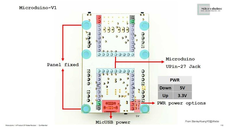
| − | **MicroUSB power | + | **MicroUSB power supply; |
| − | **3.3V constant | + | **3.3V constant voltage; |
| − | **Select the 5V or 3.3V power via PWR jumper | + | **Select the 5V or 3.3V power via PWR jumper(The default voltage is 3.3V); |
| − | **Onboard power supply indicator(5V and PWR) | + | **Onboard power supply indicator(5V and PWR). |
*Extension | *Extension | ||
| − | **Onboard reset | + | **Onboard reset button; |
| − | **Fixed OLED | + | **Fixed OLED base; |
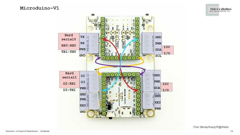
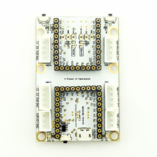
| − | **Two serial ports including (RX0,TX0)and (D2,D3) | + | **Two serial ports including (RX0, TX0)and (D2, D3); |
| − | **Two IIC | + | **Two IIC interfaces; |
| − | **Two analog button interfaces connected to | + | **Two analog button interfaces connected to A7; |
| − | **Seven analog buttons with two on the board connected to A6 and five on the stacking board connected to the interface of the base with Dupont | + | **Seven analog buttons with two on the board connected to A6 and five on the stacking board connected to the interface of the base with Dupont lines; |
**Below are two groups of sensor interfaces which can be selected and combined through jumpers. Users can choose different jumper connection as they like: | **Below are two groups of sensor interfaces which can be selected and combined through jumpers. Users can choose different jumper connection as they like: | ||
| − | *** | + | ***PWR, GND, A3 or PWR, GND, A6; |
| − | *** | + | ***PWR, D5, GND or D4, D5, GND. |
| − | [[file:Microduino-Cube-V1- | + | [[file:Microduino-Cube-V1-Pinout1Big2.jpg|800px|thumb|center|Microduino-Cube-V1-Pinout]] |
| − | [[file:Microduino-Cube-V1- | + | [[file:Microduino-Cube-V1-Pinout2Big1.jpg|800px|thumb|center|Microduino-Cube-V1-Pinout]] |
| − | [[file:Microduino-Cube-V1- | + | [[file:Microduino-Cube-V1-Pinout3Big1.jpg|800px|thumb|center|Microduino-Cube-V1-Pinout]] |
| + | [[file:Microduino-Cube-V1-Pinout4Big.jpg|800px|thumb|center|Microduino-Cube-V1-Pinout]] | ||
*Components | *Components | ||
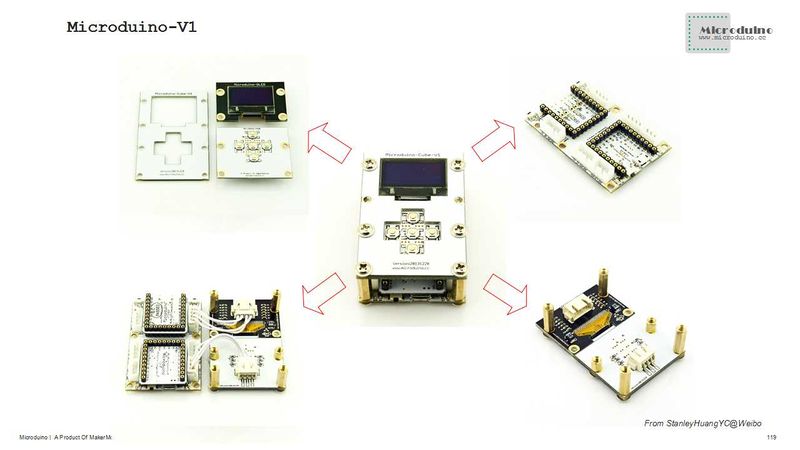
**Base board:The board with two UPIN-27 standard interfaces; | **Base board:The board with two UPIN-27 standard interfaces; | ||
| − | |||
**Overlay board: The fixed board of five analog buttons and an OLED; | **Overlay board: The fixed board of five analog buttons and an OLED; | ||
[[file:Microduino-Cube--Pinout1-Pinout4.jpg|800px|thumb|center|Microduino-Cube-S1]] | [[file:Microduino-Cube--Pinout1-Pinout4.jpg|800px|thumb|center|Microduino-Cube-S1]] | ||
==Document== | ==Document== | ||
| − | Eagle PCB : '''[[File:Microduino-Cube-V1.zip]]''' | + | Eagle PCB: '''[[File:Microduino-Cube-V1.zip]]''' |
| − | Main | + | Main components: |
*3.3V Voltage Stablizing Chip LP2985: '''[[File:LP2985.pdf]]''' | *3.3V Voltage Stablizing Chip LP2985: '''[[File:LP2985.pdf]]''' | ||
| Line 50: | Line 50: | ||
==Application== | ==Application== | ||
| − | + | You can download Microduino test program, which together with OLED to test the function of Microduino-Cube-S1's two analog buttons. Just as follows: | |
https://github.com/Microduino/Microduino_Tutorials/tree/master/Microduino_Texting/Microduino_Cube_V1_Text | https://github.com/Microduino/Microduino_Tutorials/tree/master/Microduino_Texting/Microduino_Cube_V1_Text | ||
| − | *Hardware | + | *Hardware needed: Microduino FT232R, Microduino Core, Microduino-Cube-V1 and Microduino OLED; |
| − | *Software | + | *Software needed: Microduino example program (Arduino end) and Arduino IDE(Version 1.0 and higher; |
*Open the example program in IDE, select the board "Microduino Core (Atmega328P@16M,5V)", then download directly; | *Open the example program in IDE, select the board "Microduino Core (Atmega328P@16M,5V)", then download directly; | ||
*After the download, you can see the pattern similar to the analog button on the OLED. When you press the analog buttons on the base and on the top orderly, you can simulate pressing the corresponding buttons on the OLED. | *After the download, you can see the pattern similar to the analog button on the OLED. When you press the analog buttons on the base and on the top orderly, you can simulate pressing the corresponding buttons on the OLED. | ||
Latest revision as of 10:17, 26 August 2016
| Language: | English • 中文 |
|---|
ContentsFeatures
Specifications
DocumentEagle PCB: File:Microduino-Cube-V1.zip Main components:
DevelopmentMicroduino-Cube-V1 is capable of having a fast and flexible connection and extension with other modules and sensors meeting Microduino interface standard, achieving specific function. ApplicationYou can download Microduino test program, which together with OLED to test the function of Microduino-Cube-S1's two analog buttons. Just as follows: https://github.com/Microduino/Microduino_Tutorials/tree/master/Microduino_Texting/Microduino_Cube_V1_Text
BuyHistoryPictureFrontBackVideo |


