Difference between revisions of "Microduino-Module nRF"
From Microduino Wiki
| (15 intermediate revisions by 5 users not shown) | |||
| Line 4: | Line 4: | ||
| | | | ||
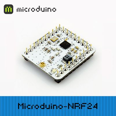
[[file:Microduino-nRF-rect.jpg|400px|thumb|right|Microduino-nRF24]] | [[file:Microduino-nRF-rect.jpg|400px|thumb|right|Microduino-nRF24]] | ||
| − | + | Microduino-nRF24 is a high-speed embedded wireless data transmission module. | |
| − | |||
| − | |||
| − | |||
| − | |||
| − | |||
| − | |||
| − | |||
|- | |- | ||
| | | | ||
==Features== | ==Features== | ||
| − | * | + | *Fully integrated link layer on the module makes it easy to develop. |
| − | * | + | *With automatic retransmission function, it can automatically detect and resend lost packets and the retransmission time and frequency can be controlled by software. |
| − | * | + | *With packets that can automatically save un-received response signals. |
| − | * | + | *With automatic reply function, the module can send response signal automatically after receiving valid data and need no reprogramming. |
| − | * | + | *Capable of setting six receiving channels' address synchronously and opening the receiving channels selectively. |
| − | *Standard pin 2. | + | *Standard pin 2.54mm spacing interface, making it convenient for embedded application. |
| − | *Small | + | *Small, stackable and economic. |
| − | *Open source hardware circuit design | + | *Open source hardware circuit design and Arduino compatible programming development environment. |
| − | * | + | *With a uniform Microduino interface standard and rich peripheral modules, it can easily connect with other Microduino modules and sensors. |
| − | *2. | + | *2.54mm(0.1 inch) pin pitch, compatible with bread boards and pegboards. |
| − | |||
==Specification== | ==Specification== | ||
| − | *Global | + | *Global open 2.4GHz ISM band with the maximum transmission power of 0DBM and free license to use. |
| − | *Low | + | *Low operation voltage: 1.9-3.6 V. |
| − | *SMA antenna, easy to | + | *SMA antenna, easy to change. |
| − | *Support six channels data | + | *Support six channels' data transmission. |
| − | *High rate: | + | *High rate: 2MBPS. Due to short transmission rate in the air, it largely reduces collision in wireless transmission. (Set 2MBPS or 256 KBPS, 1 MBPS air transmission rate with software) |
| − | *Multi-frequency | + | *Multi-point frequency: With 125 frequency points, it meets the requirement of multi-point communication and frequency hopping communication. |
| − | *Low | + | *Low consumption: With fast air transmission and startup, it greatly reduces the current consumption when communicating in the response mode. |
===Pin Description=== | ===Pin Description=== | ||
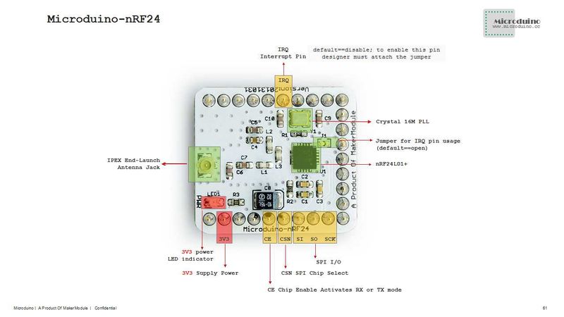
| − | [[ | + | :[[file:Micrduino-nRF24-1.jpg|800px|thumb|center|Microduino-nRF24 Spec]] |
| + | <br style="clear: left"/> | ||
{|class="wikitable" | {|class="wikitable" | ||
| Line 62: | Line 55: | ||
* Chip:'''[[File:NRF24L01 datasheet.pdf]]''' | * Chip:'''[[File:NRF24L01 datasheet.pdf]]''' | ||
* crystal:'''[[File:HCX-3SB-16M.pdf]]''' | * crystal:'''[[File:HCX-3SB-16M.pdf]]''' | ||
| − | |||
| − | |||
==Development== | ==Development== | ||
===Arduino library and support package=== | ===Arduino library and support package=== | ||
| − | *Use RF24 library, refer to RF24 library file and RF24Network library | + | *Use RF24 library, refer to RF24 library file and RF24Network library file: |
| − | ** | + | **https://github.com/Microduino/Microduino_Tutorials/tree/master/Microduino_Libraries/_03_Microduino_nRF_RF24 |
| − | ** | + | **https://github.com/Microduino/Microduino_Tutorials/tree/master/Microduino_Libraries/_03_Microduino_nRF_RF24Network |
| − | |||
==Application== | ==Application== | ||
| Line 80: | Line 70: | ||
*Prepared hardware:Microduino FT232R, Microduino Core*2, Microduino Nrf24*2; | *Prepared hardware:Microduino FT232R, Microduino Core*2, Microduino Nrf24*2; | ||
*Prepared software:Microduino example program (Arduino part), Arduino IDE(1.0 release and upper), RF24 library, RF24Network library; | *Prepared software:Microduino example program (Arduino part), Arduino IDE(1.0 release and upper), RF24 library, RF24Network library; | ||
| − | *Copy the | + | *Copy the downloaded library to libraries folod of Arduino IDE; |
*Start Arduino IED, open Microduino example program, select board "Microduino Core (Atmega328P@16M,5V)", download directly; | *Start Arduino IED, open Microduino example program, select board "Microduino Core (Atmega328P@16M,5V)", download directly; | ||
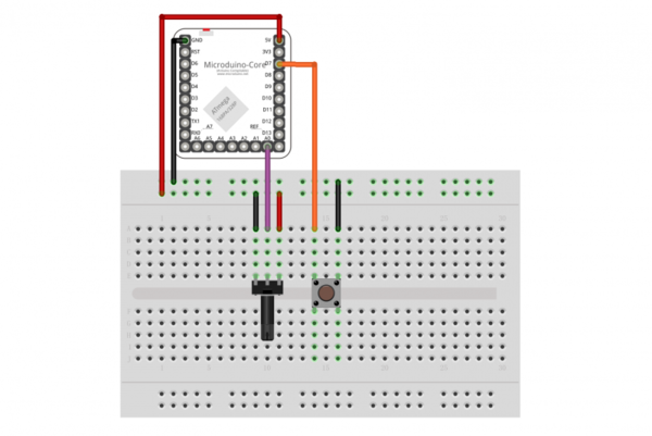
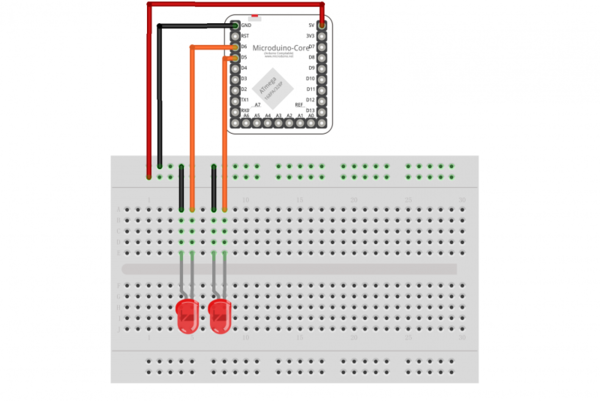
*The sending and receiving wiring picture: | *The sending and receiving wiring picture: | ||
| Line 92: | Line 82: | ||
**Sending end can control receiving end's LED by button. | **Sending end can control receiving end's LED by button. | ||
**Sending end potentiometer can control the lightness of LED for receiving end. | **Sending end potentiometer can control the lightness of LED for receiving end. | ||
| + | |||
| + | ==FQA== | ||
| + | *Does this module have the antenna? | ||
| + | **Yes. | ||
| + | *Does this module support the voltage conversion from 5V to 3.3V? | ||
| + | **Core and Core+ module doesn’t support this voltage conversion. | ||
| + | *How to control this module running in low power consumption mode or close it directly? | ||
| + | **You use the function pwerDwon() offered by Arduino library. | ||
| + | *What's the work range of this module? | ||
| + | **100 meters in the open area. | ||
==Bug== | ==Bug== | ||
| Line 100: | Line 100: | ||
==Picture== | ==Picture== | ||
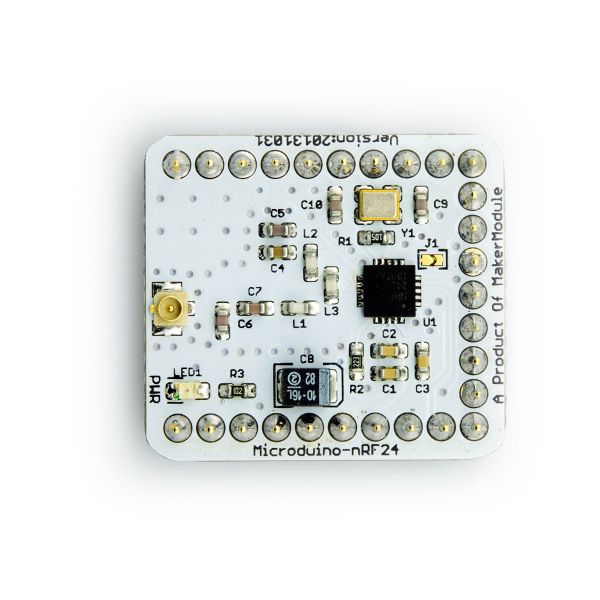
| − | [[ | + | [[file:Microduino-nRF24-t.jpg|thumb|600px|center|Microduino nRF24 Front]] |
| − | [[ | + | |
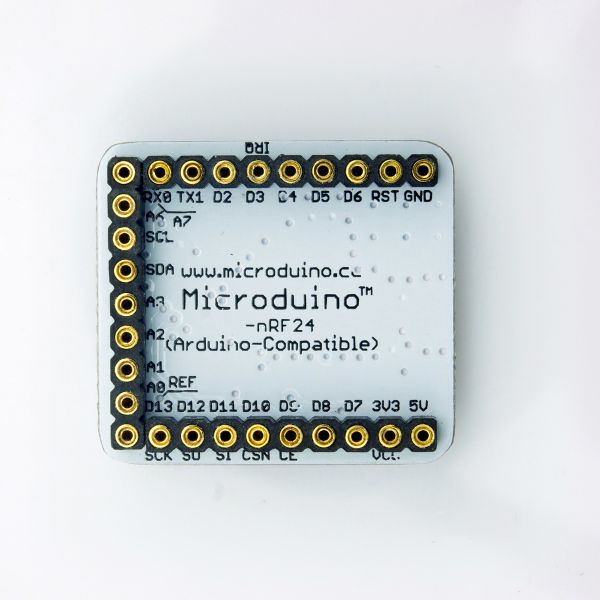
| + | [[file:Microduino-nRF24-b.jpg|thumb|600px|center|Microduino nRF24 Back]] | ||
==Video== | ==Video== | ||
|} | |} | ||
Latest revision as of 04:24, 4 August 2017
| Language: | English • 中文 |
|---|
|
Microduino-nRF24 is a high-speed embedded wireless data transmission module. | ||||||||||||||||||
ContentsFeatures
Specification
Pin Description
DocumentEagle PCB File:Microduino-nRF24.zip
Main Components
DevelopmentArduino library and support package
ApplicationDownload ProgramTest Program:File:Program Test NRF.zip Two Microduino core communicate via Nrf24
FQA
BugHistoryPictureVideo |
