Difference between revisions of "Microduino-Module GPS"
From Microduino Wiki
m (Fengfeng moved page Microduino-GPS to Microduino-Module GPS) |
|||
| (18 intermediate revisions by 2 users not shown) | |||
| Line 4: | Line 4: | ||
| | | | ||
[[file:Microduino-NEO-rect.jpg|400px|thumb|right|Microduino-NEO]] | [[file:Microduino-NEO-rect.jpg|400px|thumb|right|Microduino-NEO]] | ||
| − | This probably is the most | + | This probably is the most exquisite GPS module you've seen, which adopts UBLOX NEO-6M as its core with high sensitivity and update rate up to 5Hz. Besides, it owns a mini ceramic antenna with IPEX interface as well as a rechargeable backup battery. |
==Feature== | ==Feature== | ||
*High sensitivity | *High sensitivity | ||
| Line 23: | Line 23: | ||
*Receiving characteristics | *Receiving characteristics | ||
| − | **Channel 50,GPS L1(1575.42Mhz) C/A | + | **Channel 50,GPS L1(1575.42Mhz) C/A code,SBAS:WAAS/EGNOS/MSAS |
**Capture tracking sensitivity:-161dBm | **Capture tracking sensitivity:-161dBm | ||
| Line 45: | Line 45: | ||
**TTL,3.3V/5V microcontroller system compatible | **TTL,3.3V/5V microcontroller system compatible | ||
**Serial communication baud rate: | **Serial communication baud rate: | ||
| − | ***Microduino NEO-6M module supports several kinds of baud rate:4800,9600,38400( | + | ***Microduino NEO-6M module supports several kinds of baud rate:4800,9600,38400(default),57600; |
* Set baud rate according to two resistors of the module (R3 and R4. 1k recommended): | * Set baud rate according to two resistors of the module (R3 and R4. 1k recommended): | ||
| Line 85: | Line 85: | ||
==Development== | ==Development== | ||
| − | * Please first make sure the +3.3 v power supply current can reach 200ma. | + | '''* Please first make sure the +3.3 v power supply current can reach 200ma. Using FT232R to debug directly is not recommended for the electric current is too small.''' |
* We suggest using Microduino Core32u4 to debug the Neo-6m module: | * We suggest using Microduino Core32u4 to debug the Neo-6m module: | ||
| Line 92: | Line 92: | ||
===Use PC to debug=== | ===Use PC to debug=== | ||
| − | * | + | *When configuration directly through serial port is needed: |
** No need to stack the FT232 directly and just cross connect the FT232 and NEO-6M's RX0,TX1. | ** No need to stack the FT232 directly and just cross connect the FT232 and NEO-6M's RX0,TX1. | ||
| Line 99: | Line 99: | ||
**Please unplug the Microduino NEO-6M during the program download; | **Please unplug the Microduino NEO-6M during the program download; | ||
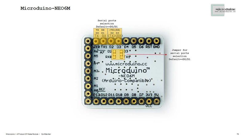
*If you want to change the jumpers to meet your requirement:Just cut the connection between the middle of two groups of pads and RX0/TX1,then connect them to D2, D3. | *If you want to change the jumpers to meet your requirement:Just cut the connection between the middle of two groups of pads and RX0/TX1,then connect them to D2, D3. | ||
| − | **If you change the jumper, you need to change the serial connection between Microduino NEO-6M and Microduino Core from "TX- | + | **If you change the jumper, you need to change the serial connection between Microduino NEO-6M and Microduino Core from "TX-RX0, RX-TX1" to: |
| − | ***TX- | + | ***TX-D2, RX-D3 (For Core+'s Serial port) |
===Arduino library and support package=== | ===Arduino library and support package=== | ||
| − | *Microduino_GPS:https://github.com/Microduino/Microduino_Tutorials/tree/master/Microduino_Libraries/_05_Microduino_GPS | + | *Microduino_GPS:[https://github.com/Microduino/Microduino_Tutorials/tree/master/Microduino_Libraries/_05_Microduino_GPS _05_Microduino_GPS] |
| − | *Microduino_OLED_U8glib:https://github.com/Microduino/Microduino_Tutorials/tree/master/Microduino_Libraries/_01_Microduino_OLED_U8glib | + | *Microduino_OLED_U8glib:[https://github.com/Microduino/Microduino_Tutorials/tree/master/Microduino_Libraries/_01_Microduino_OLED_U8glib _01_Microduino_OLED_U8glib] |
*[http://www.u-blox.com/en/evaluation-tools-a-software/u-center/u-center.html u-center-8.0] | *[http://www.u-blox.com/en/evaluation-tools-a-software/u-center/u-center.html u-center-8.0] | ||
| Line 145: | Line 145: | ||
===Test Mocroduino NEO-6M using PC=== | ===Test Mocroduino NEO-6M using PC=== | ||
| + | When to keep the default jumper wire (RX0 and TX1): | ||
====Connection method==== | ====Connection method==== | ||
| − | + | *Adopt Microduino FT232R debugging, and it cannot be directly stacked, because the pin definition of the serial port RX and TX are cnosistant of FT232 and NEO-6M, and in the normal serial port communication, TX should be cross connected with RX; | |
| − | + | **Stack FT232 and microduino together, and then connect them to PC through microUSB to download programs; | |
| − | * | ||
| − | **Stack | ||
**Use jumpers to cross connect the RX0/TX1 of FT232 and NEO-6M, that is to connect the RX0 of NEO-6M to the TX1 of FT232, and the TX1 of NEO-6M to RX0 of FT232. | **Use jumpers to cross connect the RX0/TX1 of FT232 and NEO-6M, that is to connect the RX0 of NEO-6M to the TX1 of FT232, and the TX1 of NEO-6M to RX0 of FT232. | ||
**Connect the 3V3 pin of NEO-6M module to 3V3 pin of FT232 and GND to GND for modules' power supply. | **Connect the 3V3 pin of NEO-6M module to 3V3 pin of FT232 and GND to GND for modules' power supply. | ||
| − | |||
| − | |||
| − | |||
| − | |||
| − | |||
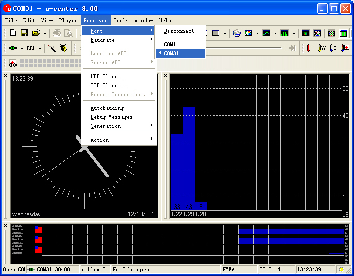
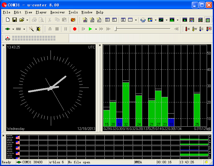
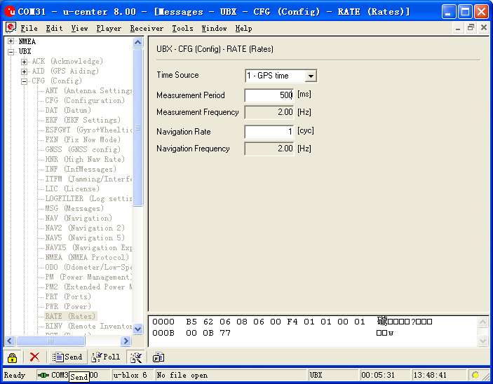
====Use u-center configuration module to update rage==== | ====Use u-center configuration module to update rage==== | ||
| Line 172: | Line 166: | ||
**After the configuration,just click the "Send" button on the bottom of the left and send the configuration to Microduino NEO-6M module. If the data update rate turns faster on other information window, that means the setup is successful. | **After the configuration,just click the "Send" button on the bottom of the left and send the configuration to Microduino NEO-6M module. If the data update rate turns faster on other information window, that means the setup is successful. | ||
[[File:U-center 04.jpg|thumb|703px|center|Configure window]] | [[File:U-center 04.jpg|thumb|703px|center|Configure window]] | ||
| + | |||
| + | |||
| + | '''Other applications:''' | ||
| + | |||
| + | Microduino KIT Sample Tutorial | ||
| + | |||
| + | [[Microduino GPS recorder-306KIT]] | ||
==FQA== | ==FQA== | ||
| − | * | + | *What should be done if there are some problems when using this module? |
| − | * | + | **Please refer to the introduction and the testing programs in wiki. |
| − | **''' | + | *How much is the power consumption of module Core together with module GPS? To choose the power supply. |
| + | **'''You need to make sure the 3.3V is above 200mA.''' | ||
| + | *How to change the jumper wire? | ||
| + | **[http://v.youku.com/v_show/id_XNzIxOTQ1NDY0.htmlhttp://v.youku.com/v_show/id_XNzIxOTQ1NDY0.html?qq-pf-to=pcqq.discussion change the jumper wire] | ||
==Buy== | ==Buy== | ||
| + | * Store '''[https://microduino.cc/product/gps@ Microduino Store]''' | ||
| + | |||
| + | |||
| + | |- | ||
| + | | | ||
==History== | ==History== | ||
| + | |||
| + | [[Microduino-NEO-6M]] | ||
==Picture== | ==Picture== | ||
Latest revision as of 04:11, 4 August 2017
| Language: | English • 中文 |
|---|
|
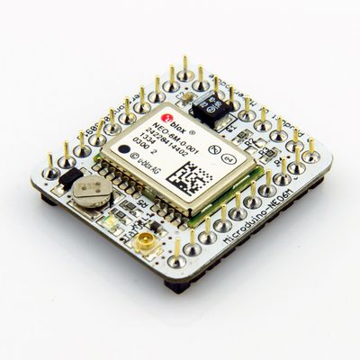
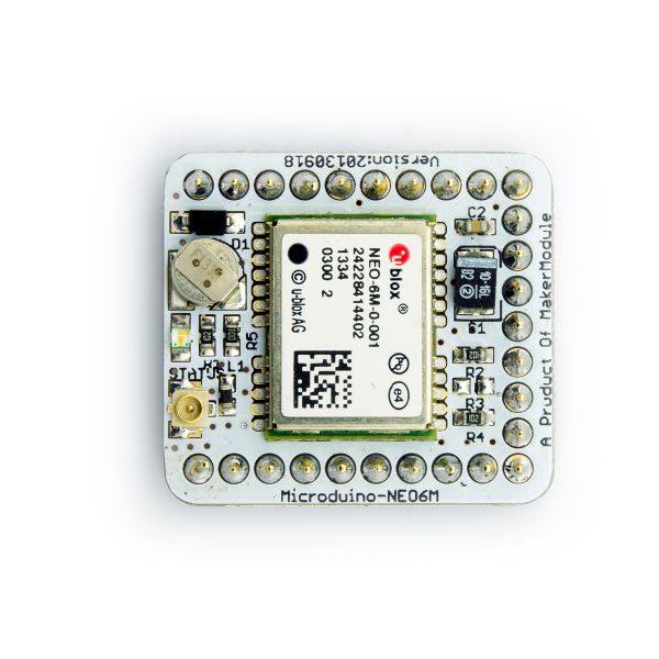
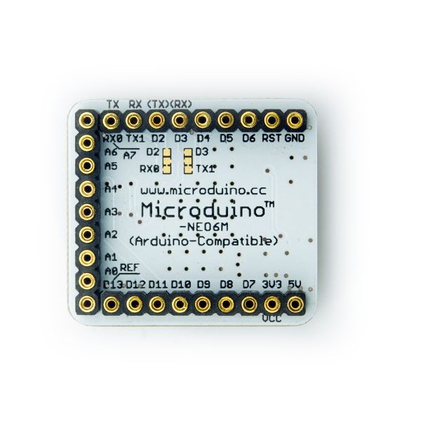
This probably is the most exquisite GPS module you've seen, which adopts UBLOX NEO-6M as its core with high sensitivity and update rate up to 5Hz. Besides, it owns a mini ceramic antenna with IPEX interface as well as a rechargeable backup battery. ContentsFeature
| |||||||||||||||||||||||||||||
Specifications
Pin Description
DocumentEagle PCB File:Microduino-NEO6M.zip
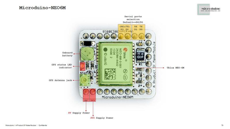
Main components
Development* Please first make sure the +3.3 v power supply current can reach 200ma. Using FT232R to debug directly is not recommended for the electric current is too small.
Use PC to debug
Use FT232R and Core to download and debug
Arduino library and support package
How to use the library
PPS Status indicator
ApplicationDownload programTest Program:File:Program Test NEO-6M.zip Test Microduino NEO-6M
Test Mocroduino NEO-6M using PCWhen to keep the default jumper wire (RX0 and TX1): Connection method
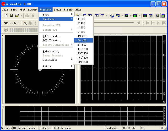
Use u-center configuration module to update rage
Microduino KIT Sample Tutorial Microduino GPS recorder-306KIT FQA
Buy
| |||||||||||||||||||||||||||||
HistoryPicture
Video |
