Difference between revisions of "Microduino-Module CoreUSB"
(→Specifications) |
|||
| (12 intermediate revisions by 4 users not shown) | |||
| Line 1: | Line 1: | ||
{{Language|Microduino-CoreUSB}} | {{Language|Microduino-CoreUSB}} | ||
| − | |||
{| style="width: 800px;" | {| style="width: 800px;" | ||
|- | |- | ||
| | | | ||
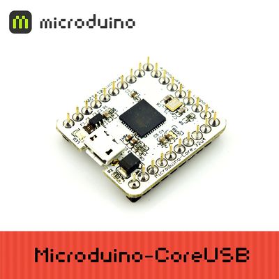
| − | [[File:Microduino-core32U4-rect.jpg|400px|thumb|right|Microduino- | + | [[File:Microduino-core32U4-rect.jpg|400px|thumb|right|Microduino-CoreUSB]] |
| − | Microduino CoreUSB | + | Microduino-CoreUSB 8-bit microcontroller development board with the ATMEGA32U4 series as the core,and it is a open-source controller module compatible with Arduino Leonardo. |
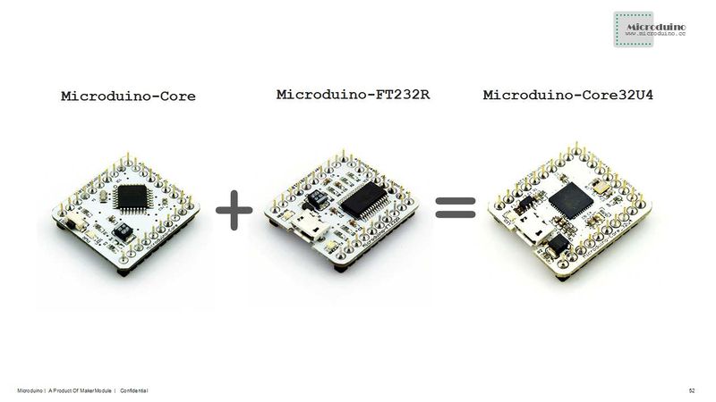
| − | The difference between Microduino-CoreUSB and Microduino-core | + | The difference between Microduino-CoreUSB and Microduino-core and Microduino-core+ is that the Microduino-CoreUSB contains a microcontroller and USB communication, equivalent to (Microduino-core + Microduino-USBTTL), and its pins conform to the Microduino specification. |
| − | + | Microduino uses java , the development environment of C language, same with Arduino. Players can use Arduino IDE, cooperating with software such as Flash or Processing, with Microduino and other electronic components,modules and sensors to make many funny interactive works. | |
| − | Microduino | ||
==Features== | ==Features== | ||
| − | * | + | *It contains microcontroller and USB communication, so you can directly download programs through the USB port, having no more need of Microduino-USBTTL; |
| − | *USB overcurrent protection | + | *USB overcurrent protection; |
| − | *Small, cheap, stackable, | + | *Small, cheap, stackable, and open; |
| − | *Open source hardware circuit design, compatible with | + | *Open-source hardware circuit design, and programming development environment compatible with Arduino; |
| − | * | + | *Same with Arduino, Microduino can use ISP download way, to program to「bootloader」 flexibly; |
| − | * | + | *Unified Microduino interface specification, and abundant peripheral modules, can be connected and extended quickly, conveniently, and flexibly with other modules and sensors conforming to the Microduino interface specification; |
| − | *2.54 | + | *2.54 spacing Female Header interface is convenient to integrate into the hole plate. |
| − | |||
| − | |||
| − | + | ==Specification== | |
| − | |||
| − | |||
| − | |||
| − | |||
| − | |||
| − | |||
| − | |||
| − | |||
| − | |||
| − | |||
{|class="wikitable" | {|class="wikitable" | ||
|- | |- | ||
| − | |Flash||32 | + | |Flash||32 KB(ATMEGA32U4). 4 KB during it is used to guide the program. |
|- | |- | ||
|SRAM||2.5 KB(ATMEGA32U4) | |SRAM||2.5 KB(ATMEGA32U4) | ||
| Line 42: | Line 28: | ||
|EEPROM||1 KB(ATMEGA32U4) | |EEPROM||1 KB(ATMEGA32U4) | ||
|- | |- | ||
| − | |Clock | + | |Clock speed||16 MHz |
| + | |} | ||
| + | |||
| + | |||
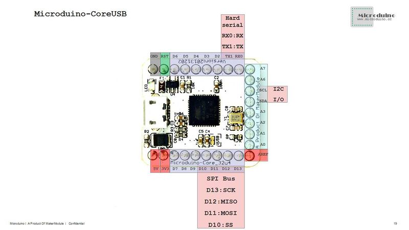
| + | * Digital I/O There are 22 digital input/output terminals: | ||
| + | ** Labeled on the module of D0~D13, and A0~A7. | ||
| + | * Analog I/O There are 10 analog input/output: | ||
| + | ** Labeled on thee module of A0, A1, A2, A3, A6, A7, D8(A8), D9(A9), D3(A10) and D4(A11); | ||
| + | ** Each offers a 10-bit resolution( that is 0~1024). By default, the measurement range of the analog voltage is the value from GND to VCC; | ||
| + | ** Please refer to'''[http://www.arduino.cc/en/Reference/AnalogRead analogRead()]''' function. | ||
| + | * PWM support. There are 8: | ||
| + | ** Labeled on the module of respectively SCL, D3, D4, D5, D6, D7, D8 and D9. | ||
| + | ** Please refer to'''[http://www.arduino.cc/en/Reference/AnalogWrite analogWrite()]''' function. | ||
| + | * Serial port support. There are 2: | ||
| + | ** USB virtual serial port Serial; | ||
| + | ** Labeled on the module of Serial1 [D0(RX), D1(TX)]. | ||
| + | * SPI support. There is one: | ||
| + | ** Labeled on the module of D13(SCK), D12(MISO), D11(MOSI), D10(SS). | ||
| + | * I2C support. There is one: | ||
| + | ** Labeled on the module of SDA(D18),SCL(D19). | ||
| + | * External interrupt support. There are 5: | ||
| + | ** Labeled on the module of SCL(interrupt0), SDA(interrupt1), D0(interrupt2), D1(interrupt3), and D2(interrupt4). | ||
| + | ** Please refer to'''[http://arduino.cc/en/Reference/AttachInterrupt attachInterrupt()]''' function. | ||
| + | * Support the ISP download function. | ||
| + | * Support AREF end. | ||
| + | |||
| + | *Instruction of the pins: | ||
| + | |||
| + | {|class="wikitable" | ||
| + | | align="center" style="background:#f0f0f0;"|'''Pin''' | ||
| + | | align="center" style="background:#f0f0f0;"|'''Original Pin Name''' | ||
| + | | align="center" style="background:#f0f0f0;"|'''Map Pin Name''' | ||
| + | | align="center" style="background:#f0f0f0;"|'''Digital Pin''' | ||
| + | | align="center" style="background:#f0f0f0;"|'''Analog Pin''' | ||
| + | | align="center" style="background:#f0f0f0;"|'''interrupt''' | ||
| + | | align="center" style="background:#f0f0f0;"|'''PWM''' | ||
| + | | align="center" style="background:#f0f0f0;"|'''Serial''' | ||
| + | | align="center" style="background:#f0f0f0;"|'''SPI''' | ||
| + | | align="center" style="background:#f0f0f0;"|'''I2C''' | ||
| + | | align="center" style="background:#f0f0f0;"|'''Power''' | ||
| + | |- | ||
| + | | 1||VCC||+5V||||||||||||||||+5V | ||
| + | |- | ||
| + | | 2||VCC||+3V3||||||||||||||||+3.3V | ||
| + | |- | ||
| + | | 3||(OC0A/OC1C/#RTS)PB7||D7||D7||||||yes|||||||| | ||
| + | |- | ||
| + | | 4||(OC1B/0C4B/ADC13)PB6||D8||D8||A8||||yes|||||||| | ||
| + | |- | ||
| + | | 5||(OC1A/#OC4B/ADC12)PB5||D9||D9||A9||||yes|||||||| | ||
| + | |- | ||
| + | | 6||(SS)PB0||D10||D10||||||||||SS|||| | ||
| + | |- | ||
| + | | 7||(PDI/MOSI)PB2||D11||D11||||||||||MOSI|||| | ||
| + | |- | ||
| + | | 8||(PDO/MISO)PB3||D12||D12||||||||||MISO|||| | ||
| + | |- | ||
| + | | 9||(SCK)PB1||D13||D13||||||||||SCK|||| | ||
| + | |- | ||
| + | | 10||AREF||AREF|||||||||||||||| | ||
| + | |- | ||
| + | | 11||(ADC7/TDI)PF7||A0||D14||A0|||||||||||| | ||
| + | |- | ||
| + | | 12||(ADC6/TDO)PF6||A1||D15||A1|||||||||||| | ||
| + | |- | ||
| + | | 13||(ADC5/TMS)PF5||A2||D16||A2|||||||||||| | ||
| + | |- | ||
| + | | 14||(ADC4/TCK)PF4||A3||D17||A3|||||||||||| | ||
| + | |- | ||
| + | | 15||(SDA/INT1)PD1||SDA||D18||||1||||||||SDA|| | ||
| + | |- | ||
| + | | 16||(OC0B/SCL/INT0)PD0||SCL||D19||||0||yes||||||SCL|| | ||
| + | |- | ||
| + | | 17||(ADC1)PF1||A6||D20||A6|||||||||||| | ||
| + | |- | ||
| + | | 18||(ADC0)PF0||A7||D21||A7|||||||||||| | ||
| + | |- | ||
| + | | 19||(RXD1/AIN1/INT2)PD2||D0||D0||||2||||1(RX)|||||| | ||
| + | |- | ||
| + | | 20||(TXD1/INT3)PD3||D1||D1||||3||||1(TX)|||||| | ||
| + | |- | ||
| + | | 21||(INT6/AIN0)PE6||D2||D2||||4|||||||||| | ||
| + | |- | ||
| + | | 22||(T1/#OC4D/ADC9)PD6||D3||D3||A10||||yes|||||||| | ||
| + | |- | ||
| + | | 23||(T0/OC4D/ADC10)PD7||D4||D4||A11||||yes|||||||| | ||
| + | |- | ||
| + | | 24||(OC3A/#OC4A)PC6||D5||D5||||||yes|||||||| | ||
| + | |- | ||
| + | | 25||(ICP3/CLK0/OC4A)PC7||D6||D6||||||yes|||||||| | ||
| + | |- | ||
| + | | 26||RESET||RST|||||||||||||||| | ||
| + | |- | ||
| + | | 27||GND||GND||||||||||||||||GND | ||
|} | |} | ||
| + | |||
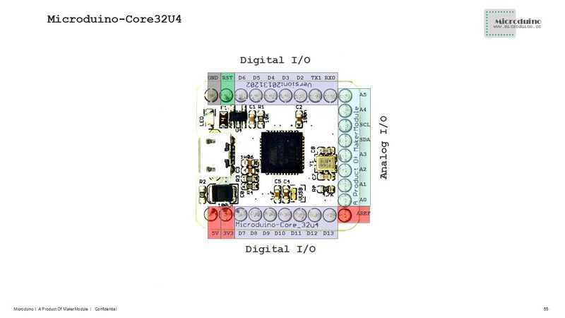
[[file:Microduino-Core32U4-Pinout.jpg|800px|thumb|center|Microduino-Core32U4-Pinout]] | [[file:Microduino-Core32U4-Pinout.jpg|800px|thumb|center|Microduino-Core32U4-Pinout]] | ||
| − | [[file:Microduino-Core32U4- | + | [[file:Microduino-Core32U4-Pinout1Big1.jpg|800px|thumb|center|Microduino-Core32U4-Pinout]] |
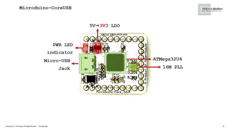
| − | [[file:Microduino-Core32U4- | + | [[file:Microduino-Core32U4-Pinout2Big1.jpg|800px|thumb|center|Microduino-Core32U4-Pinout]] |
[[file:Microduino-Core32U4-Pinout3.jpg|800px|thumb|center|Microduino-Core32U4-Pinout]] | [[file:Microduino-Core32U4-Pinout3.jpg|800px|thumb|center|Microduino-Core32U4-Pinout]] | ||
==Document== | ==Document== | ||
Eagle PCB '''[[File:Microduino-core32U4.zip]]''' | Eagle PCB '''[[File:Microduino-core32U4.zip]]''' | ||
| − | * | + | *The main components used in Microduino-core32U4. |
| − | * | + | * MCU: '''[[File:ATmega32U4.zip]]''' |
==Development== | ==Development== | ||
| − | * | + | * 1.Downloading programs to Microduino-CoreUSB , players need to use '''[[Microduino-USBTTL]]''' module. |
| − | * | + | * 2.The tutorial of setting the development environment and installing the driver is as following: |
| − | + | **'''[[Microduino Getting start]]''' | |
| + | |||
| + | * Program Microduino BootLoader | ||
| + | ** If BootLoader is damaged, you need to use Arduino UNO or existing Microduino to program bootloader to the damaged Microduino; | ||
| + | **Players can refer to: '''[[Do you know how to use Arduino UNO to program bootloader to Microduino-Core?]]'''. | ||
| − | ** | + | ==Application== |
| + | * [https://www.microduino.cc/project Microduino Project cases] | ||
| + | * [https://www.microduino.cc/wiki/index.php?title=Microduino_(Arduino%E5%85%BC%E5%AE%B9%E6%9D%BF%EF%BC%89%E6%95%99%E7%A8%8B Microduino Applications tutorials] | ||
| + | * [http://www.geek-workshop.com/thread-4558-1-1.html Microduino applications of the internet of things] [From geek-workshop.com] | ||
| − | |||
| − | |||
| − | |||
| − | |||
| − | == | + | |
| − | * | + | ==FAQ== |
| − | * | + | *Can this module be used together with Microduino-GPRS/GSM? |
| − | * | + | **Yes, it can. |
| − | + | ||
| − | == | + | ==Purchase== |
==History== | ==History== | ||
| − | + | '''[[Microduino-Core32U4]]''' | |
| − | == | + | ==Map storage== |
| + | ===Frontage=== | ||
[[file:Microduino-Core32U4-F.JPG|thumb|600px|center|Microduino-Core32U4 Front]] | [[file:Microduino-Core32U4-F.JPG|thumb|600px|center|Microduino-Core32U4 Front]] | ||
| − | == | + | ===Backface=== |
[[file:Microduino-Core32U4-b.JPG|thumb|600px|center|Microduino-Core32U4 Back]] | [[file:Microduino-Core32U4-b.JPG|thumb|600px|center|Microduino-Core32U4 Back]] | ||
==Video== | ==Video== | ||
|} | |} | ||
Latest revision as of 03:48, 4 August 2017
| Language: | English • 中文 |
|---|
|
Microduino-CoreUSB 8-bit microcontroller development board with the ATMEGA32U4 series as the core,and it is a open-source controller module compatible with Arduino Leonardo. The difference between Microduino-CoreUSB and Microduino-core and Microduino-core+ is that the Microduino-CoreUSB contains a microcontroller and USB communication, equivalent to (Microduino-core + Microduino-USBTTL), and its pins conform to the Microduino specification. Microduino uses java , the development environment of C language, same with Arduino. Players can use Arduino IDE, cooperating with software such as Flash or Processing, with Microduino and other electronic components,modules and sensors to make many funny interactive works. Contents[hide]Features
Specification
DocumentEagle PCB File:Microduino-core32U4.zip
Development
Application
FAQ
PurchaseHistoryMap storageFrontageBackfaceVideo |
