Difference between revisions of "Microduino-10DOF"
From Microduino Wiki
| (42 intermediate revisions by 7 users not shown) | |||
| Line 1: | Line 1: | ||
| + | {{Language|Microduino-10DOF}} | ||
{| style="width: 800px;" | {| style="width: 800px;" | ||
|- | |- | ||
| | | | ||
| − | [[file:Microduino- | + | [[file:Microduino-10DOF-rect.jpg|400px|thumb|right|Microduino-10DOF]] |
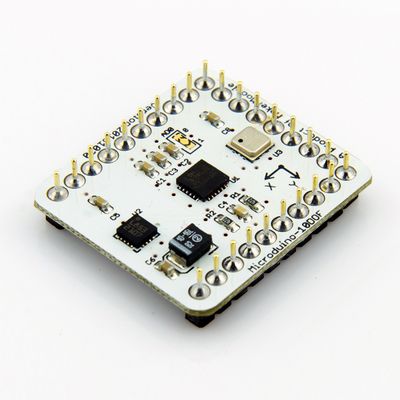
| − | '''[[Microduino-10DOF]]''' | + | '''[[Microduino-10DOF]]'''integrates four sensors including one sensor of 3-axis gyroscope and 3-axis accelerometer(MPU6050), one magnetic field strength sensor(HMC5883L) and a digital barometer sensor(BMP180). This module adopts I2C interface, widely used in automation control, such as aeromodelling,self-balancing car. |
| − | |||
| − | |||
| − | |||
| − | |||
| − | |||
| − | |||
| − | |||
| − | |||
| − | |||
| − | |||
|- | |- | ||
| | | | ||
| − | |||
==Specification== | ==Specification== | ||
| Line 24: | Line 14: | ||
'''Magnetic field intensity sensor:HMC5883L''' | '''Magnetic field intensity sensor:HMC5883L''' | ||
| − | *HMC5883L | + | *HMC5883L contains the most advanced high-resolution HMC118X series magnetic-resistive sensor; |
| − | *Honeywell patents | + | *Integrated circuit with Honeywell patents includes an amplifier, automatic degaussing actuator, offset calibration and a 12-bit AD converter which can control the accuracy of the compass to the range of 1 ° ~ 2 °; |
| − | * | + | *A simple IIC serial bus interface. |
| − | '''Digital Pressure | + | '''Digital Pressure Sensor:BMP180''' |
| − | *BMP180 | + | *BMP180 comprises a resistive pressure sensor, an AD converter, and a control unit; |
| − | * | + | **The control unit includes E2PROM and I2C interfaces. BMP180 transmits uncompensated temperature and pressure values. E2PROM stores 176bit individual standard data, which are used for compensation of temperature dependence and other sensor parameters. |
| − | *Available range: 300hPa to 1100hPa ( | + | *Available range: 300hPa to 1100hPa (corresponding sea level to -500m -- +9000 m) |
| − | *Lowest absolute accuracy can be achieved 0.03hPa | + | *Lowest absolute accuracy can be achieved--0.03hPa |
*UP = pressure data (16 to 19bit) | *UP = pressure data (16 to 19bit) | ||
*UT = temperature data (0 to 15bit) | *UT = temperature data (0 to 15bit) | ||
| Line 41: | Line 31: | ||
'''Triaxial accelerometer + three-axis gyro sensor:MPU6050''' | '''Triaxial accelerometer + three-axis gyro sensor:MPU6050''' | ||
| − | *It integrates a 3-axis MEMS gyroscope, three-axis MEMS accelerometer, and a scalable | + | *It integrates a 3-axis MEMS gyroscope, a three-axis MEMS accelerometer, and a scalable DMP (Digital Motion Processor); |
| − | *Digital output 6 or 9 axis rotation matrix, quaternion, Euler angles format (EulerAngleforma) data fusion algorithms; | + | *Digital output for 6 or 9 axis rotation matrix, quaternion, Euler angles format (EulerAngleforma) data fusion algorithms; |
| − | *With 131LSBs / | + | *With 131LSBs / °sec sensitivity and whole cell sensing range is ± 250, ± 500, ± 1000 and ± 2000 ° / sec of 3-axis angular velocity sensor (gyroscope); |
| − | * | + | *3-axis accelerometer is programmable control and the range is ± 2g, ± 4g, ± 8g and ± 16g; |
| − | * | + | *Reduces the impact of setting given and sensor drift by removing the shaft between the accelerator and the gyro sensitivity, ; |
| − | * | + | *The complexity of data fusion algorithms, sensors synchronization, load position sensors can be reduced by useing Digital motion processing (DMP: DigitalMotionProcessing) engine |
| − | *A digital output | + | *A temperature sensor with digital output; |
| − | *Gyro operational current: 5mA, gyroscope standby current: 5uA; accelerator operation current: 500uA, accelerator power saving mode current: 40uA @ 10Hz up to 400kHz fast mode of | + | *Gyro operational current: 5mA, gyroscope standby current: 5uA; accelerator operation current: 500uA, accelerator power saving mode current: 40uA @ 10Hz up to 400kHz fast mode of IIC. |
|- | |- | ||
| | | | ||
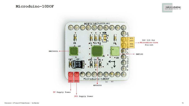
| + | [[File:10DOF-Pinout-1.jpg|800px|thumb|center|Microduino-10DOF-Pinout1]] | ||
| − | |||
| − | |||
| − | |||
| − | |||
| − | |||
| − | |||
| − | |||
| − | |||
| − | |||
| − | |||
| − | |||
| − | |||
| − | |||
| − | |||
|- | |- | ||
| | | | ||
| − | |||
== Development == | == Development == | ||
| − | ''' | + | '''Arduino Libraries and support packages''' |
| − | + | *Microduino_10DOF:https://github.com/Microduino/Microduino_Tutorials/tree/master/Microduino_Libraries/_05_Microduino_10DOF | |
| − | * | + | *【BMP180 Library'''[https://github.com/jrowberg/i2cdevlib/tree/master/Arduino/BMP085 github Download]''' , '''[https://github.com/adafruit/Adafruit-BMP085-Library github Download]''' 】 |
| − | * | + | *【HMC5883L Library'''[https://github.com/jrowberg/i2cdevlib/tree/master/Arduino/HMC5883L github Download]''' 】 |
| − | * | + | *【MPU6050 Library'''[https://github.com/jrowberg/i2cdevlib/tree/master/Arduino/MPU6050 github Download]''' 】 |
| − | * | + | *【I2Cdev Library'''[https://github.com/jrowberg/i2cdevlib/tree/master/Arduino/I2Cdev github Download]''' 】 |
| − | * | + | *【U8glib Library'''[http://code.google.com/p/u8glib/ google Download ]''' 】 |
|- | |- | ||
| | | | ||
| − | |||
| − | |||
| − | |||
== Applications == | == Applications == | ||
| − | ''' | + | '''Download''' |
| − | * | + | *MultiWii and source code :https://github.com/Microduino/Microduino_Tutorials/tree/master/Microduino%20Axis |
| − | * | + | *OLED tests 10dof source code:[[File:Program Test 10DOF.zip]] |
| − | ''' | + | '''Use open source of MWC test 10dof module''' |
| − | * | + | *The hardware need to be prepared:Microduino FT232R、Microduino Core、Microduino 10dof; |
| − | * | + | *The software need to be prepared:MultiWii(Linux/Mac/Windows)、MultiWii source code(Arduino)、Arduino IDE(above 1.0 version); |
| − | * | + | *First use IED open MultiWii.ino in MultiWii directory,the project can be load directly. The provided source code has already been configured for Microduino 10dof.Select board "Microduino Core (Atmega328P@16M,5V)",and then downloaded directly; |
| − | * | + | *Turn on the PC. Take the Windows as example,Execution "MultiWiiConf.exe" in MultiWiiConf \ application.windows32 directory,select the corresponding serial port, then click "Start" to test module. |
| − | ''' | + | '''Use OLED test 10dof module''' |
| − | * | + | *The hardware need to be prepare:Microduino FT232R、Microduino Core、Microduino 10dof、Microduino OLED; |
| − | * | + | *The software need to be prepare:Arduino IDE(above 1.0 version)、Microduino provide test source code(Arduino)、BMP180 Library、HMC5883 LLibrary、MPU6050 Library、I2Cdev Library、U8glib Library; |
| − | * | + | *The downloaded libraries should be put into library folder within Arduino IDE's installation folder; |
| − | * | + | *Start Arduino IED,Open the test code that Microduino provided,select board "Microduino Core (Atmega328P@16M,5V)",and then downloaded directly; |
| − | * | + | *After the download, please pay attention to the OLED is complete: |
| − | * | + | **Top row is used to test HM5883L,The module is placed in the horizontal position, turn the module can be observed that pointer always points to an angle; |
| − | * | + | **The middle row is used to test BMP180, observing pressure and temperature data; |
| − | * | + | **The last line is used to test MPU6050, tilt module,then you can observe the ball rolling toward the corresponding direction. |
| Line 120: | Line 93: | ||
| | | | ||
| − | + | ==FQA== | |
| − | + | *How to run 10DOF test program in Mac? | |
| − | + | **Running a Mac Osx 10.9.3 with IDE 1.0.5 with boads.txt from Microduino see | |
| + | '''http://www.microduino.cc/wiki/index.php?title=Arduino_IDE_Microduino Hardware Support Package''' | ||
| + | **Download test program from Microduino-10DOF | ||
| + | '''http://www.microduino.cc/wiki/index.php?title=Microduino-10DOF''' | ||
| + | **Modified somewhat and running on a Core+See Inclinomter | ||
| + | '''https://plus.google.com/u/0/communities/117933845827174624649/stream/e9bf5dd3-74d2-4e17-af1c-8a54c6bfb9e8''' | ||
==History== | ==History== | ||
| − | * | + | *April 8,2013,@laoPanorz found SI pin doesn't connect to VDD in HMC5883l. |
| − | * | + | *Feb 28,2013, test release publish, no major issue. |
| − | * | + | *Feb 18,2013, the first official release layout. |
|- | |- | ||
| | | | ||
| + | |||
==Pictures== | ==Pictures== | ||
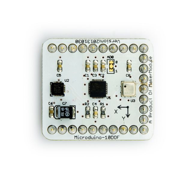
| − | :[[file:Microduino-10DOF- | + | :[[file:Microduino-10DOF-t.jpg|thumb|600px|center|Microduino 10DOF Front]] |
<br style="clear: left"/> | <br style="clear: left"/> | ||
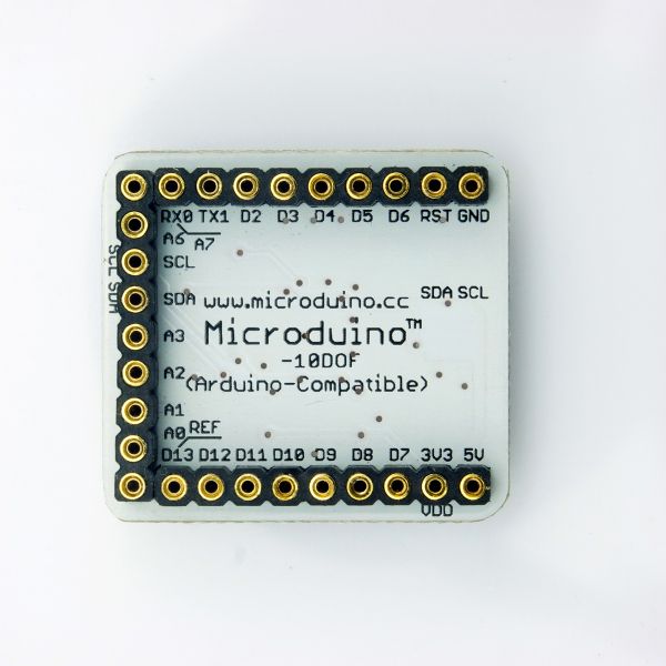
| − | :[[file:Microduino-10DOF- | + | :[[file:Microduino-10DOF-b.jpg|thumb|600px|center|Microduino 10DOF Back]] |
<br style="clear: left"/> | <br style="clear: left"/> | ||
* Testing video: [http://v.youku.com/v_show/id_XNTIzMTY3MTU2.html Microduino-10DOF MPU6050 Testing] | * Testing video: [http://v.youku.com/v_show/id_XNTIzMTY3MTU2.html Microduino-10DOF MPU6050 Testing] | ||
Latest revision as of 22:57, 9 November 2016
| Language: | English • 中文 |
|---|
|
Microduino-10DOFintegrates four sensors including one sensor of 3-axis gyroscope and 3-axis accelerometer(MPU6050), one magnetic field strength sensor(HMC5883L) and a digital barometer sensor(BMP180). This module adopts I2C interface, widely used in automation control, such as aeromodelling,self-balancing car.
|
SpecificationMagnetic field intensity sensor:HMC5883L
Digital Pressure Sensor:BMP180
Triaxial accelerometer + three-axis gyro sensor:MPU6050
|
|
|
|
DevelopmentArduino Libraries and support packages
|
ApplicationsDownload
Use open source of MWC test 10dof module
Use OLED test 10dof module
|
FQA
http://www.microduino.cc/wiki/index.php?title=Arduino_IDE_Microduino Hardware Support Package
http://www.microduino.cc/wiki/index.php?title=Microduino-10DOF
History
|
Pictures
|


