Difference between revisions of "Connection Method for New Version"
(Created page with " {| style="width: 800px;" | colspan="2" | *You need to use AT instruction to set up some parameters via the serial port. So you can refer to the following module handbook: [...") |
|||
| (8 intermediate revisions by 3 users not shown) | |||
| Line 4: | Line 4: | ||
*You need to use AT instruction to set up some parameters via the serial port. So you can refer to the following module handbook: | *You need to use AT instruction to set up some parameters via the serial port. So you can refer to the following module handbook: | ||
| − | [[File: | + | [[File:Microduino-Ble.pdf]] |
*Module Needed | *Module Needed | ||
{|class="wikitable" | {|class="wikitable" | ||
| Line 25: | Line 25: | ||
|Microduino-BT||Microduino-USBTTL | |Microduino-BT||Microduino-USBTTL | ||
|- | |- | ||
| − | | | + | |D4||TX1 |
|- | |- | ||
| − | | | + | |D5||RX0 |
|- | |- | ||
|3V3 ||3V3 | |3V3 ||3V3 | ||
| Line 36: | Line 36: | ||
[[File:BT-USBTTL-new-1.jpg|600px|center|thumb]] | [[File:BT-USBTTL-new-1.jpg|600px|center|thumb]] | ||
| − | |||
You need to open Arduino IDE serial monitor or downloaded CommAssistant and set up as follows: Baud rate: 9600; Data bit: 8; Stop bit: 1; Check bit: None. Besides, please make sure AT instruction ended with new line, 0x0D 0x0A and “\r\n”. | You need to open Arduino IDE serial monitor or downloaded CommAssistant and set up as follows: Baud rate: 9600; Data bit: 8; Stop bit: 1; Check bit: None. Besides, please make sure AT instruction ended with new line, 0x0D 0x0A and “\r\n”. | ||
| − | |||
*Slave machine setup | *Slave machine setup | ||
| Line 48: | Line 46: | ||
[[File:Microduino-BLE-connect-1.png|center]] | [[File:Microduino-BLE-connect-1.png|center]] | ||
| − | + | ||
| − | + | Since the BT is the slave machine by default, you need to charge it with other power supply device and wait for the connection of the host machine. | |
| − | |||
*Host machine setup | *Host machine setup | ||
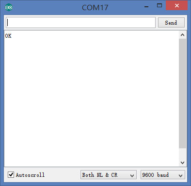
Open the serial monitor, select baud rate 9600 and “Both NL & CR” and input “AT” in the serial port data sending box. If the return is “ok”, it means the serial communication of the module is fine. | Open the serial monitor, select baud rate 9600 and “Both NL & CR” and input “AT” in the serial port data sending box. If the return is “ok”, it means the serial communication of the module is fine. | ||
| − | |||
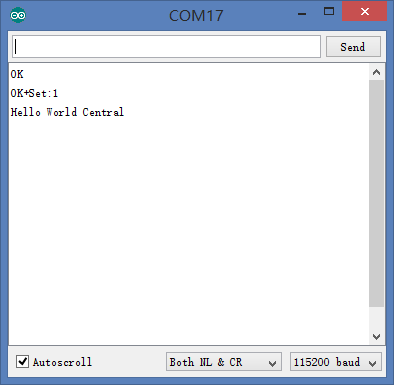
Change the mode of the host machine, input “AT+ROLE1” in the serial port data sending box. If the return shows “OK+Set:1 Hello World Central”, then the host machine setup is successful. | Change the mode of the host machine, input “AT+ROLE1” in the serial port data sending box. If the return shows “OK+Set:1 Hello World Central”, then the host machine setup is successful. | ||
| Line 63: | Line 59: | ||
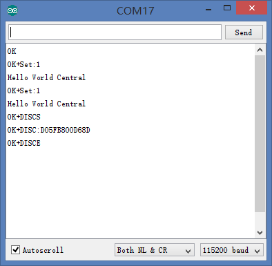
Search slave machine device, input “AT+DISC?” in the serial data sending box and go back to your slave machine BT MAC address. | Search slave machine device, input “AT+DISC?” in the serial data sending box and go back to your slave machine BT MAC address. | ||
[[File:Microduino-BLE-connect-5.png|center]] | [[File:Microduino-BLE-connect-5.png|center]] | ||
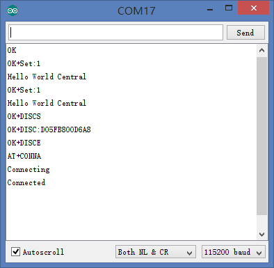
| − | Connect the slave machine, input “AT+COND05FB800D68D” in the serial data sending box and have the connection with the slave machine. If the connection goes well, the slave machine will output “Connected” and the host machine will show “Connected” after about 23 seconds after updating parameters, meaning the BT connection is successful and the system enters | + | Connect the slave machine, input “AT+COND05FB800D68D” in the serial data sending box and have the connection with the slave machine. If the connection goes well, the slave machine will output “Connected” and the host machine will show “Connected” after about 23 seconds after updating parameters, meaning the BT connection is successful and the system enters transmission mode. |
[[File:Microduino-BLE-connect-6.png|center]] | [[File:Microduino-BLE-connect-6.png|center]] | ||
| + | |} | ||
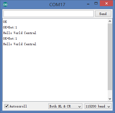
| + | Power off the slave machine and set power-on connection mode for host machine. Enter “AT+IMME1” in serial data sending box and when it returns to “OK+Set:1 Hello World Central”, it means the setup is successful. This, it can be connected even when powers off. | ||
| + | [[File:Microduino-BLE-connect-4.png|center]] | ||
| + | You can also control AT instruction via core if you think dupont line connection is boring. | ||
| + | *Here we adopt D4, D5 serial port to debug. | ||
| + | Program: | ||
| + | <source lang="cpp"> | ||
| + | #include <SoftwareSerial.h> | ||
| + | SoftwareSerial mySerial(4, 5); // RX, TX | ||
| + | |||
| + | void setup() | ||
| + | { | ||
| + | // Open serial communications and wait for port to open: | ||
| + | Serial.begin(9600); | ||
| + | // set the data rate for the SoftwareSerial port | ||
| + | mySerial.begin(9600); | ||
| + | } | ||
| + | |||
| + | void loop() // run over and over | ||
| + | { | ||
| + | if(Serial.available()) | ||
| + | { | ||
| + | mySerial.write(Serial.read()); | ||
| + | } | ||
| + | if(mySerial.available()) | ||
| + | { | ||
| + | Serial.write(mySerial.read()); | ||
| + | } | ||
| + | } | ||
| + | </source> | ||
| + | You can connect according to steps above after the program download. | ||
|} | |} | ||
Latest revision as of 01:42, 22 December 2015
You need to open Arduino IDE serial monitor or downloaded CommAssistant and set up as follows: Baud rate: 9600; Data bit: 8; Stop bit: 1; Check bit: None. Besides, please make sure AT instruction ended with new line, 0x0D 0x0A and “\r\n”.
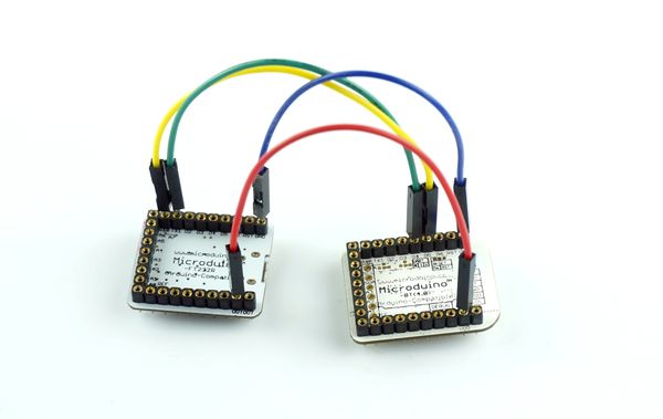
Select a module as the slave machine and connect the wire according to pin. Open the serial monitor, select 9600 baud rate and “Both NL & CR” and input “AT” in the serial data sending box and enter. If the return is “OK”, it means the serial communication of the module has no problem.
Since the BT is the slave machine by default, you need to charge it with other power supply device and wait for the connection of the host machine.
Open the serial monitor, select baud rate 9600 and “Both NL & CR” and input “AT” in the serial port data sending box. If the return is “ok”, it means the serial communication of the module is fine. Change the mode of the host machine, input “AT+ROLE1” in the serial port data sending box. If the return shows “OK+Set:1 Hello World Central”, then the host machine setup is successful. Set power-on connection mode, input “AT+IMME1” in the serial port data sending box. If the return show “OK+Set:1 Hello World Central”, it means the setup is successful. Search slave machine device, input “AT+DISC?” in the serial data sending box and go back to your slave machine BT MAC address. Connect the slave machine, input “AT+COND05FB800D68D” in the serial data sending box and have the connection with the slave machine. If the connection goes well, the slave machine will output “Connected” and the host machine will show “Connected” after about 23 seconds after updating parameters, meaning the BT connection is successful and the system enters transmission mode. | ||||||||||||||||||||||||||
Power off the slave machine and set power-on connection mode for host machine. Enter “AT+IMME1” in serial data sending box and when it returns to “OK+Set:1 Hello World Central”, it means the setup is successful. This, it can be connected even when powers off.
You can also control AT instruction via core if you think dupont line connection is boring.
- Here we adopt D4, D5 serial port to debug.
Program:
#include <SoftwareSerial.h>
SoftwareSerial mySerial(4, 5); // RX, TX

void setup()
{
  // Open serial communications and wait for port to open:
  Serial.begin(9600);
  // set the data rate for the SoftwareSerial port
  mySerial.begin(9600);
}

void loop() // run over and over
{
  if(Serial.available())
  {
    mySerial.write(Serial.read());
  }
  if(mySerial.available())
  {
    Serial.write(mySerial.read());
  }
}
You can connect according to steps above after the program download. |}
