Difference between revisions of "Microduino-Joypad Getting started"
From Microduino Wiki
| (2 intermediate revisions by 2 users not shown) | |||
| Line 49: | Line 49: | ||
| − | *Applied in: '''Remote control of the | + | *Applied in: '''Remote control of the Quadcopter ''' |
**Adopt Microduino-CoreRF as the core module. | **Adopt Microduino-CoreRF as the core module. | ||
**The CoreRF comes with 2.4G communication function and need no other core to work with. | **The CoreRF comes with 2.4G communication function and need no other core to work with. | ||
| − | * Applied in : '''Motion control of the | + | * Applied in : '''Motion control of the Quadcopter ''' |
**Adopt CoreRF as the core module. | **Adopt CoreRF as the core module. | ||
** The CoreRF comes with 2.4G communication function and need no other core to work with. | ** The CoreRF comes with 2.4G communication function and need no other core to work with. | ||
| Line 133: | Line 133: | ||
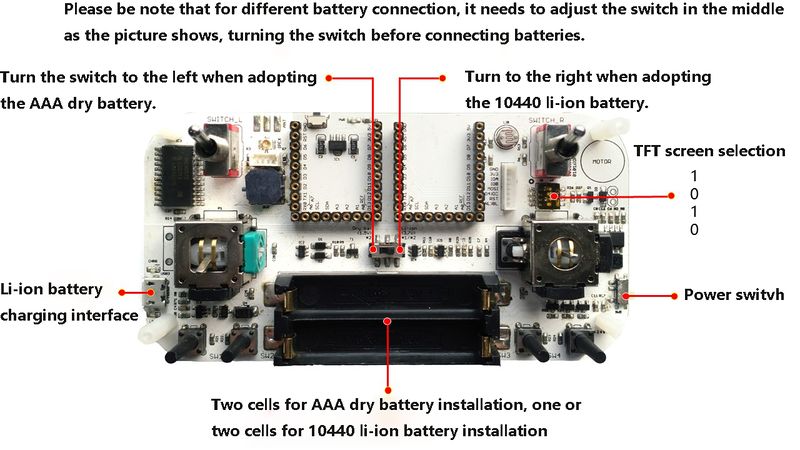
*'''For the battery usage, please refer to the picture below, toggle the switch (in the battery mode) to the right position and then connect into battery. ''' | *'''For the battery usage, please refer to the picture below, toggle the switch (in the battery mode) to the right position and then connect into battery. ''' | ||
| − | [[File: | + | [[File:Joypadstep01_1.jpg|center|800px]] |
*After the connection, please make sure you plugged in the USB cable to "activate" the power management circuit of the Joypad. | *After the connection, please make sure you plugged in the USB cable to "activate" the power management circuit of the Joypad. | ||
| − | *Then, you can control the power switch of the Joypad normally. | + | *Then, you can control the power switch of the Joypad normally. |
===Power Quantity Reminder and Charging(only for 10440 Li-ion battery) === | ===Power Quantity Reminder and Charging(only for 10440 Li-ion battery) === | ||
| Line 147: | Line 147: | ||
==Step-4: Buildup== | ==Step-4: Buildup== | ||
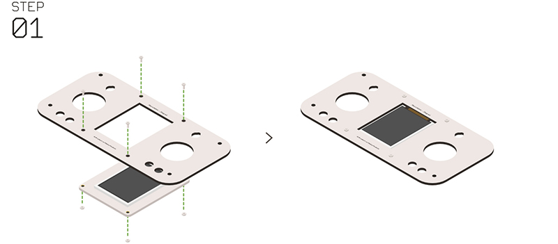
| − | *'''Step 1''' | + | *'''Step 1''': |
*Insert the Microduino-TFT into the panel of the Microduino-Joypad. | *Insert the Microduino-TFT into the panel of the Microduino-Joypad. | ||
*Fixate them with'''nylon screws ''' and '''nylon nuts ''', make sure the Microduino-TFT installation is right. | *Fixate them with'''nylon screws ''' and '''nylon nuts ''', make sure the Microduino-TFT installation is right. | ||
[[File:Joypadstep1.jpg|center|800px]] | [[File:Joypadstep1.jpg|center|800px]] | ||
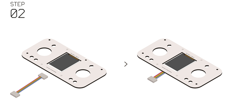
| − | *'''Step 2''' | + | *'''Step 2''': |
*Insert the cable in the Microduino-TFT. | *Insert the cable in the Microduino-TFT. | ||
[[File:Joypadstep2.jpg|center|800px]] | [[File:Joypadstep2.jpg|center|800px]] | ||
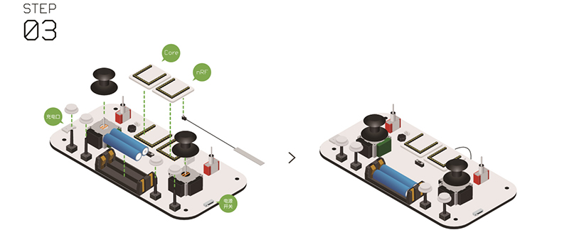
| − | *'''Step 3''' | + | *'''Step 3''': |
*Install the communication module and the core module into the UPIN27 interface of the Joypad's baseboard. | *Install the communication module and the core module into the UPIN27 interface of the Joypad's baseboard. | ||
*Make sure the "battery", "two rocker covers " and "four white keys " installed correct. | *Make sure the "battery", "two rocker covers " and "four white keys " installed correct. | ||
[[File:Joypadstep3.jpg|center|800px]] | [[File:Joypadstep3.jpg|center|800px]] | ||
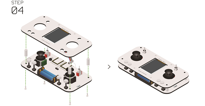
| − | *'''Step 4''' | + | *'''Step 4''': |
*Connect the other side of the Microduino-TFT cable to the corresponding interface the baseboard. | *Connect the other side of the Microduino-TFT cable to the corresponding interface the baseboard. | ||
*Install the nylon columns. | *Install the nylon columns. | ||
*Fixate the columns with nylon screws. | *Fixate the columns with nylon screws. | ||
[[File:Joypadstep4.jpg|center|800px]] | [[File:Joypadstep4.jpg|center|800px]] | ||
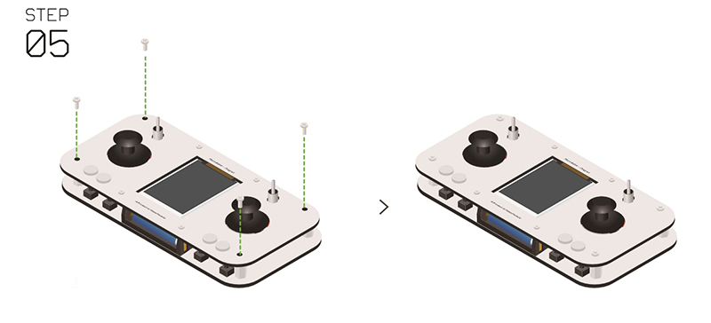
| − | *'''Step 5''' | + | *'''Step 5''': |
*Fixate the four corners of the panel. | *Fixate the four corners of the panel. | ||
[[File:Joypadstep5.jpg|center|800px]] | [[File:Joypadstep5.jpg|center|800px]] | ||
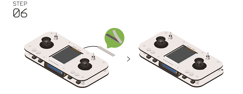
| − | *'''Step 6''' | + | *'''Step 6''': |
*After the installation of the antenna, congratulations! you just completed the hardware buildup of the Joypad. | *After the installation of the antenna, congratulations! you just completed the hardware buildup of the Joypad. | ||
[[File:Joypadstep6.jpg|center|800px]] | [[File:Joypadstep6.jpg|center|800px]] | ||
| Line 176: | Line 176: | ||
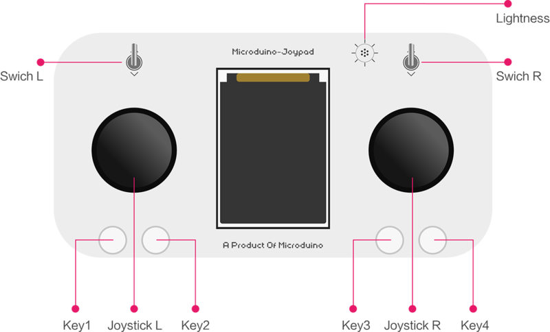
*Two rockers: Joystick L、Joystick R | *Two rockers: Joystick L、Joystick R | ||
*Two switches: Switch L、Switch R | *Two switches: Switch L、Switch R | ||
| − | *Four keys: | + | *Four keys: Key1, Key2, Key3, Key4 |
*One Light sensor: | *One Light sensor: | ||
| Line 199: | Line 199: | ||
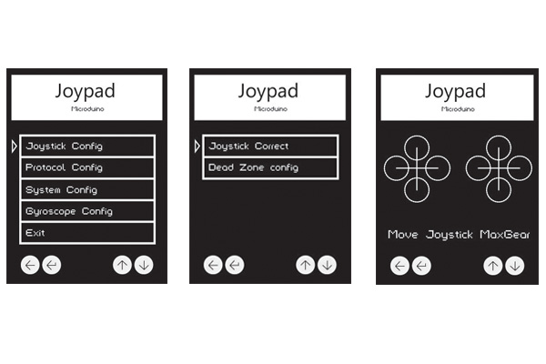
*Select "Joystick Config-Joystick Correct" and enter the calibration mode of the Joystick. | *Select "Joystick Config-Joystick Correct" and enter the calibration mode of the Joystick. | ||
**After that, you'll see two crosses at the beginning. | **After that, you'll see two crosses at the beginning. | ||
| − | **Move the left and the right rockers around to the | + | **Move the left and the right rockers around to the up most. |
| − | **And you'll see cycles around the crosses. When the cycle gets to its largest, it indicates the rocker has been turned to the | + | **And you'll see cycles around the crosses. When the cycle gets to its largest, it indicates the rocker has been turned to the up most. |
[[File:Step2摇杆校准.jpg|600px|center|]] | [[File:Step2摇杆校准.jpg|600px|center|]] | ||
===="Dead zone" setting for the Joystick ==== | ===="Dead zone" setting for the Joystick ==== | ||
| Line 233: | Line 233: | ||
== FAQ== | == FAQ== | ||
| − | * | + | *Q: '''Does Joypad support AAA batteries? ''' |
| − | ** | + | **A: Yes, it'll need two. But we don't recommend that. |
| − | * | + | *Q: '''Why don't you recommend AAA batteries? ''' |
| − | ** | + | **A: The battery protection and low power indicator of the Joypad are designed for the 3.7V Li-ion battery. Two cells of AAA batteries may trigger circuit protection and cause the illusion of no electricity, |
| − | * | + | *Q: '''What battery does Joypad recommend? ''' |
| − | ** | + | **A: Single or two cells of 10440 3.7V Li-ion batteries. |
| − | * | + | *Q: '''What core module does we need to control the Quadrobot? ''' |
| − | ** | + | **A: CoreRF, which comes with communication function and therefore, it needs no other communication modules. |
|} | |} | ||
Latest revision as of 05:47, 30 September 2016
| Language: | English • 中文 |
|---|
Contents[hide]
Overview
Project Background
Bill of Material
Module Selection
Bill of Material
Step-1:ProgrammingSource Code DownloadDownload the program from the address below: [Joypad_RC] Stacking Modules
Configuring the Environment
Program Download
Step-2: Reference Voltage
Step-3:Power-on via batteryBattery Specification Supportable
Activate the Power Management Circuit
Power Quantity Reminder and Charging(only for 10440 Li-ion battery)
Step-4: Buildup
Step-5: Key Description
Step-6: Channel/Operation Description
Step-7: Menu Configuration InstructionsEnter Configuration Mode
Joystick ConfigurationCalibration of the Joystick
"Dead zone" setting for the Joystick
Communication Protocol ConfigurationCommunication Mode
Channel Configuration of the Quadro Mode
Channel Configuration of nRF Mode
System ConfigurationThem Configuration of the Display Screen
Display Screen Spinning Configuration
MCU Reference Voltage Configuration
Motion Configuration
Exit Configuration Mode
FAQ
|
