Difference between revisions of "Applause Enthusiasm Detection"
| Line 26: | Line 26: | ||
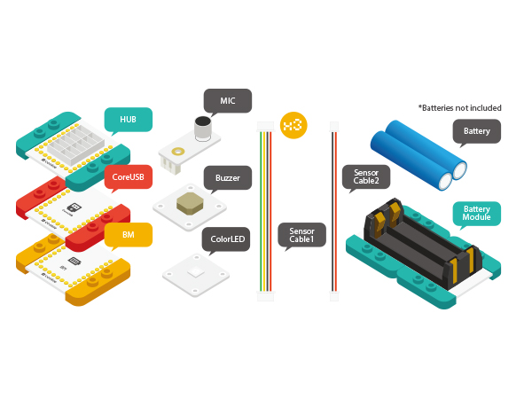
|[[Microduino-Buzzer]]||1||Buzzer sensor | |[[Microduino-Buzzer]]||1||Buzzer sensor | ||
|- | |- | ||
| − | | [[Microduino-BM]]||1||Batery management |} | + | | [[Microduino-BM]]||1||Batery management |
| + | |} | ||
[[File: Applause_heat_module.jpg|600px|center]] | [[File: Applause_heat_module.jpg|600px|center]] | ||
Revision as of 04:03, 6 November 2015
| Language: | English • 中文 |
|---|
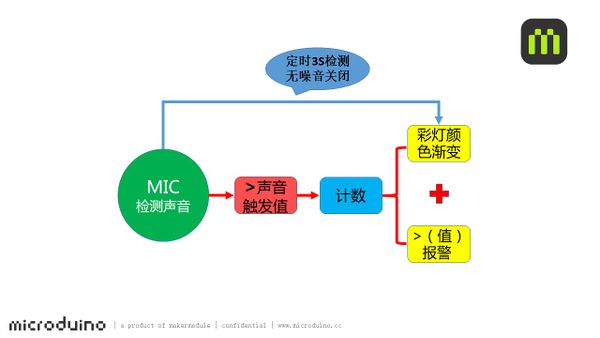
ContentsObjectiveDetection of applause: The longer the sound duration lasts, the stronger the light becomes. When the light gets to the brightest, the buzzer gives an alarm. PrincipleWith MIC sound detection sensor to detect the applause sound, when the sound is louder than the pre-set sound value, the device starts counting, the longer the time gets, the greater the data becomes while the color of the lights are becoming brighter. When it reaches a certain value, the brightness of the light turns to the maximum and at the same time, the buzzer starts giving an alarm. The system detects sound every three seconds. When there is no sound, the light and the alarm will stop. Equipment
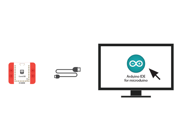
Preparation
Program Description
#define PIN 4

Adafruit_NeoPixel strip = Adafruit_NeoPixel(6, PIN, NEO_GRB + NEO_KHZ800);

#define mic_pin A0
#define buzzer_pin 6
#define voice 400
  if (voice_data > voice)
  {
    num++;
    if (num > 255)
    {
      num = 255;
      buzzer();
    }
    colorWipe(strip.Color(num, 0, 0));
    //delay(10);
    Serial.println(num);
    time = millis();
  }
  if (millis() - time > 3000 )
  {
    voice_data = analogRead(mic_pin);
    if (voice_data < voice)
    {
      colorWipe(strip.Color(0, 0, 0));
      num = 10;
      noTone(buzzer_pin);
    }
    time = millis();
  }
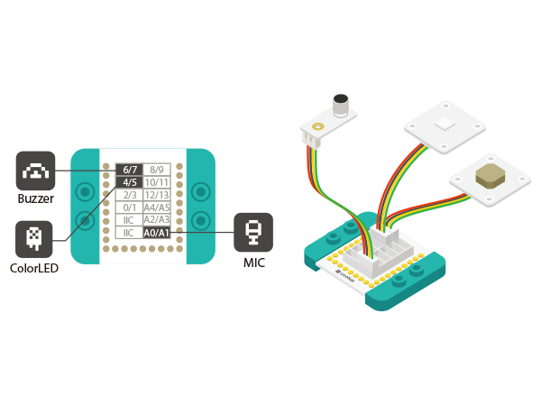
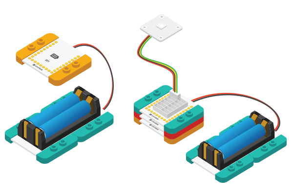
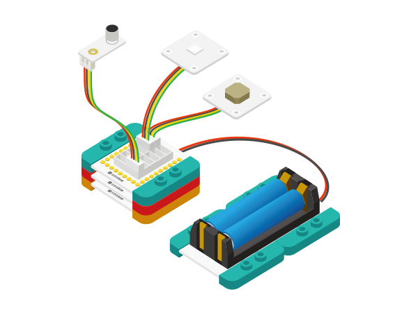
Hardware Buildup
If modules cannot work normally, please try to power off and re-connect. ResultThe greater the applause sound is, the brighter the LED light gets. when the light gets to the brightest, the Buzzer will give an alarm. When the sound is below the pre-set value and lasts for three seconds, the light and the alarm will stop. You can also build a beautiful shell with LEGO boards since mCookie can be freely stacked with LEGO boards. Video |
