Difference between revisions of "Microduino-Module WIFI,ESP"
(→Development) |
(→Firmware programming instructions) |
||
| Line 92: | Line 92: | ||
==Firmware programming instructions== | ==Firmware programming instructions== | ||
1:welds point marked "down", or use wire to connect GND and GPIO0(written on the | 1:welds point marked "down", or use wire to connect GND and GPIO0(written on the | ||
| + | back of the board of the vias 0) | ||
| − | |||
2:Recommend use USBTTL transfer serial directly, you need connect four wires to | 2:Recommend use USBTTL transfer serial directly, you need connect four wires to | ||
| − | |||
transfer serail port. | transfer serail port. | ||
{| class="wikitable" | {| class="wikitable" | ||
| Line 110: | Line 109: | ||
|} | |} | ||
If you use the core module programming firmware, please do the serial converter with | If you use the core module programming firmware, please do the serial converter with | ||
| − | |||
Core+ module, can not use Core, because WIFI (ESP) serial port is (D2, D3) pin 115200 | Core+ module, can not use Core, because WIFI (ESP) serial port is (D2, D3) pin 115200 | ||
| − | |||
baud rate, the corresponding Core is soft serial port, baud rate less than 115200. | baud rate, the corresponding Core is soft serial port, baud rate less than 115200. | ||
The USBTTL, Core+ stack, download the program to the Core+ module. | The USBTTL, Core+ stack, download the program to the Core+ module. | ||
| Line 156: | Line 153: | ||
4:Open debugging tools, test AT command make sure whether the firmware burn | 4:Open debugging tools, test AT command make sure whether the firmware burn | ||
| − | |||
successful | successful | ||
5:Finally remove the weld on "down" or disconnect the wire which connect GND and | 5:Finally remove the weld on "down" or disconnect the wire which connect GND and | ||
| − | + | GPIO0(written on the | |
| − | GPIO0(written on the | ||
==Questions== | ==Questions== | ||
Revision as of 03:27, 18 October 2015
| Language: | English • 中文 |
|---|
|
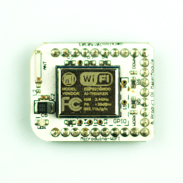
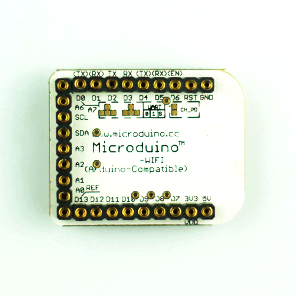
Microduino-WiFi (ESP) module is a WiFi communication module, through the serial port Transmission data to Core / Core + / CoreUSB core module for communication, you can connect other WiFi devices. ContentsFeatures
Specifications
Common AT commands
attention to select "\ r \ n".
DocumentsSupport AT command configuration control:File:ESP8266 WiFi Module Quick Start Guide v 1.0.4.pdf Development
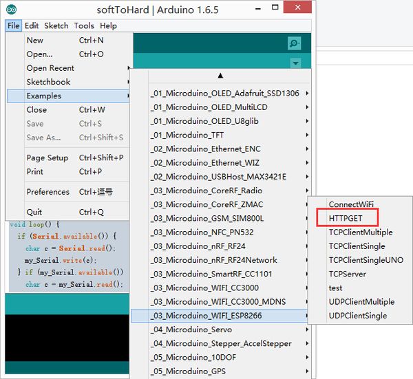
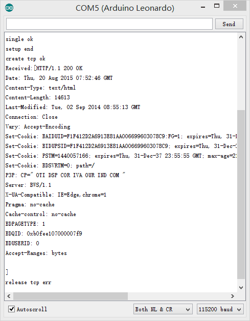
Use Microduino IDE-->example-->_03_microduino_WiFi_ESP8266-->HTTPGET program test is OK. We have set SSID (wifi name) and pass (password) places in the code, change your wifi password
insert USB line into the Microduino-USBttl, other side of USB line insert into computer, start Arduino IDE, The above program is copied to the IDE, the tool (tools) -> Board (Board) is selected Microduino Core, and the tools (tools) -> Serial Port (Serial) select the corresponding serial number. After clicking the top left corner IDE √ button to compile the program, after the end of the compilation click -> button is programmed to the board;
ApplicationRelated Applications: WiFi Weather Stations Firmware programming instructions1:welds point marked "down", or use wire to connect GND and GPIO0(written on the back of the board of the vias 0) 2:Recommend use USBTTL transfer serial directly, you need connect four wires to transfer serail port.
If you use the core module programming firmware, please do the serial converter with Core+ module, can not use Core, because WIFI (ESP) serial port is (D2, D3) pin 115200 baud rate, the corresponding Core is soft serial port, baud rate less than 115200. The USBTTL, Core+ stack, download the program to the Core+ module. #define my_Serial Serial1 //Core+ or CoreUSB
void setup() {
Serial.begin(115200);
my_Serial.begin(115200);
}
void loop() {
if (Serial.available()) {
char c = Serial.read();
my_Serial.write(c);
} if (my_Serial.available()) {
char c = my_Serial.read();
Serial.write(c);
}
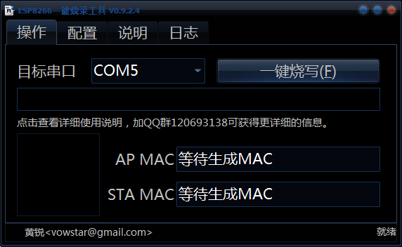
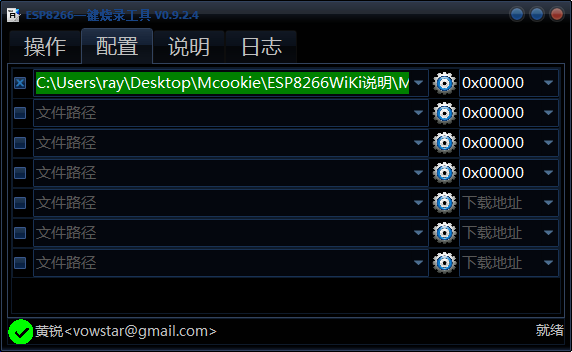
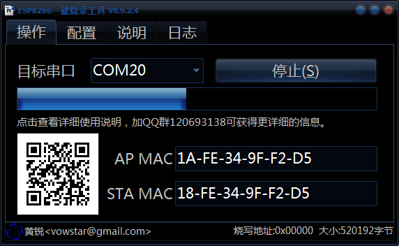
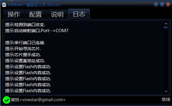
}soft serial port to hard seral port:File:SoftToHard-V2.rar 3:Connect USB, open burn firmware tool, set firmware address update firmware. Firmware tool software:File:ESP8266Flasher.rar Firmware file:File:MicroduinoESP8266.rar Connect USB to PC, your firmware tool software will show below: setup as below: v0.9.5.2 AT Firmware-------------0x00000 Find right firmware file in floder and fill right address return operation tab, and click burn
5:Finally remove the weld on "down" or disconnect the wire which connect GND and GPIO0(written on the QuestionsGallery |

