Difference between revisions of "Microduino-【BT】"

From Microduino Wiki
Jump to: navigation, search
(Application)
(How to Connect Two Microduino-BT Modules)
Line 125: Line 125:
  
 
===[[How to Connect Two Microduino-BT Modules]]===
 
===[[How to Connect Two Microduino-BT Modules]]===
 +
{| style="width: 800px;"
 +
|-
 +
|
 +
*You need to use AT instruction to set up some parameters via the serial port. So you can refer to the following module handbook:
 +
[[File:Bluetooth40 en.pdf]]
 +
*Module Needed
 +
{|class="wikitable"
 +
|-
 +
|Related Hardware||Number||Function
 +
|-
 +
|Microduino-BT||2||For communication connection
 +
|-
 +
|Microduino-USBTTL||1||For serial port communication debugging
 +
|-
 +
|Dupont line ||4||For circuit connection
 +
|-
 +
|USB cable ||2||For power supply
  
 +
|-
 +
|}
 +
*We must set one module as the master machine and another as the slave machine. The master machine will search the requirement of the slave machine and then match them. When we start to build the hardware and connect Microduino-BT and Microduino-USBTTL, we need to connect four wires: 
 +
{|class="wikitable"
 +
|-
 +
|Microduino-BT||Microduino-USBTTL
 +
|-
 +
|RX0||TX1
 +
|-
 +
|TX1||RX0
 +
|-
 +
|3V3 ||3V3
 +
|-
 +
|GND ||GND
 +
|-
 +
|}
 +
 +
[[File:BT-USBTTL-1.jpg|600px|center|thumb]]
 +
[[File:BT-USBTTL-2.jpg|600px|center|thumb]]
 +
 +
*'''Slave Machine Parameter Configuration:
 +
**Build the circuit according to the schematic and supply the power through USB cable;
 +
**Open Arduino editor, choose the right COM port, open the serial port debugging, or you can use other Com debug assistant. 
 +
**First, choose the serial port baud rate as 9600 , set the mode as “No line terminator”. Click “send” or “enter” after inputting “AT” in the serial port data sending box, you’ll receive “OK” at the data receiving end, meaning your BT module can be set via AT instruction. 
 +
 +
Notice: If there is no return value, you need to change the baud rate to 115200. It is probably the unmatched baud rate that leads to failed communication. Baud rate setup can refer to the module handbook above. 
 +
**Check and set a BT module under slave mode(The default is the slave mode):
 +
***Click “send” or “enter” after inputting “AT+ROLE” in the serial port sending box, you can set it under the slave mode if it returns as “OK+Get0” and under the host mode if it returns as “OK+Get1”. So, you need to set the slave mode via “AT+ROLE0” instruction. 
 +
**Check the work type of the slave machine--“Power to work instantly”.
 +
***Click “send” or “enter” after inputting “AT+IMME?” in the serial port data sending box, you can know that “Power to work instantly” if it returns as “OK=Get1”. Otherwise, you need to set it as “Power to work instantly” mode via “AT+IMME?” instruction. After finishing configuring the slave machine parameter, you just need to get it powered.
 +
 +
*'''Master Machine Parameter Configuration:''' 
 +
**Check and set another BT module to be under the master machine mode:
 +
***Click “send” or “enter” after inputting “AT+ROLE?” in the serial port data sending box. If it returns to be “OK+Get0”, then it is under the slave mode. You need to set it under the host mode through “AT+ROLE1” instruction. Generally, by this time you can get your Bluetooth connected. The host machine will search the slave devices and connect them automatically. 
 +
 +
 +
**If it fails to connect, please check whether the work type of the host machine is “Power to wait ” (Default).
 +
***Click “send” or “enter” after inputting “AT+IMME?” in the serial port data sending box. If it returns to be “OK+ Get1, then it is under the mode of “Power to work instantly”. So, you need to set it under the mode of “Power to wait” through “AT+IMME0” instruction. 
 +
**If it still can’t connect under the mode of “Power to wait”, it is probably the host machine has connected other Bluetooth devices.(Since it will try to connect the preserved slave devices instantly, this may lead to disconnection with the existing devices.)  So, you can use “AT+CLEAR” to clear the originally stored connection information. In this way, it can enter the search state and search once again for device and then connect. 
 +
 +
**If it still can not be connected, you can try to connect devices in the fixed Bluetooth MAC address
 +
 +
**Connect Microduino-USBTTL with the slave machine, configure the host machine, check MAC address of the slave machine and save the address.
 +
***Click “send” or “enter” after inputting “AT+ADDR?” in the serial port data sending box. If it returns to be address “OK+ADDR:MAC(XXX)”, please don’t forget the address since the host machine needs to make connection through the address. After configuring the slave parameter, the only thing you need is to get it charged. 
 +
***Connect Microduino-USBTTL and the host machine, configure the host machine, set the work type of the host--”Power to work instantly”.
 +
***Just input “AT+CONXXX” in the serial port data sending box. “XXX” is the MAC address you keep in mind. Then, click “send” or “enter”. If it returns to be “OK”, it means a successful connection and you can see two Bluetooth indicators don’t blink. It it can’t connect to the fixed devices, it’ll enter the state of search and at this time, you can try “AT+RESET” to restart the module and reconnect.
 +
**After it is connected, if you cut off the device, you can’t reconnect it once again. You need to restart the serial monitor, set the work type of the host machine--”Power to wait”. Thus, you can get it connected every time it gets powered off.
 +
|}
  
 
===Note:If you use Android device to debug, you need to make sure the system should be version 4.3 or higher so that Microduino-BT can be detected.===
 
===Note:If you use Android device to debug, you need to make sure the system should be version 4.3 or higher so that Microduino-BT can be detected.===

Revision as of 01:55, 22 August 2014

Language: English  • 中文
Microduino-Shield BT4.0

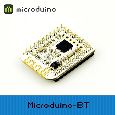
Microduino-Shield BT 4.0 module is a plug-in device that supports Bluetooth 4.0 low energy standard. Microduino-Shield BT 4.0 module is a bluetooth serial port transparent transmission module, using the 27 PIN standard Microduino interface, supporting the Arduino board and derivatives, such as Microduino core. The module is designed by player ogre_c.

Features

  • Microduino-Shield BT4.0 adopts U type 27 PIN interface of Microduino, combining with other Microduino modult to use;
  • Microduino-Shield BT4.0 chooses the HM-10 BLE as the bluetooth core module;
  • TI CC2540 chip with 256Kb space;
  • Support AT instruction, capable of updating baud rate, device name,paring code and other related parameters as needed, flexible to use;
  • Small, cheap, stackable;
  • Open source hardware circuit design, compatible with the Arduino IDE development environment for programming;
  • With uniformed Microduino interface standard and rich peripheral modules, it is flexible and convenient to have a quick connection and extension with other corresponding Microduino modules and sensors;
  • 2.54 pitch row female connector for easy integration into breadboard.

Specifications

  • Communication form: serial transmission;
  • Power supply:+3.3VDC 50mA;
  • Bluetooth protocol:Bluetooth Specification V4.0 BLE;
  • Service support:Central & Peripheral UUID FFE0,FFE1;
  • Frequency:2.4GHz ISM band;
  • Modulation mode:GFSK(Gaussian Frequency Shift Keying);
  • Power of transmission:≤4dBm;
  • Sensitivity:≤-84dBm at 0.1% BER;
  • Transmission rate:
    • Asynchronous: 6 kbps;
    • Synchronous: 6 kbps;
  • State indicator:
    • Two states:
      • Flashing means that the module has been powered but not matched well.
      • Always lighting means that the module has been matched well and has started communication.
    • By the indicator, it is very easy to the status of the module, which is conveniently.

Documents

Eagle PCB File:Microduino-BT Shield.zip

Main component

Development

Serial communication requirements

  • Default serial configuration:
    • Baud rate: 9600
    • No check
    • Data bits: 8
    • Stop bit: 1
  • As for Arduino IDE serial monitor:
    • Set at:"No line terminator"、"9600baud"
  • For other serial debug software:
    • Baud rate: 9600
    • No check
    • Data bits: 8
    • Stop bit: 1
  • We suggest using Microduino-Core32u4 to debug this BT module:
    • Microduino-Core32u4 module can use the USB to simulate the serial 0, and BT uses the 32u4's serial 1 (RX0,TX1), so you don't need to change the existing jumper (RX0,TX1) and it won't impact program download or the serial port's function.
  • Microduino Shield BT4.0 uses the default serial RX0,TX1 to communicate with Core module, so it can be directly connected with Microduino FT232.

Use PC to debug

  • When debugging directly through the serial port:
    • No need to stack the FT232 directly, and just cross connect the FT232 and BT4.0's RX0,TX1.

Use FT232R、Core to download and debug

  • If it keeps using the default jumper (RX0、TX1):
    • Unplug the Microduino Shield BT4.0 during downloading the program;
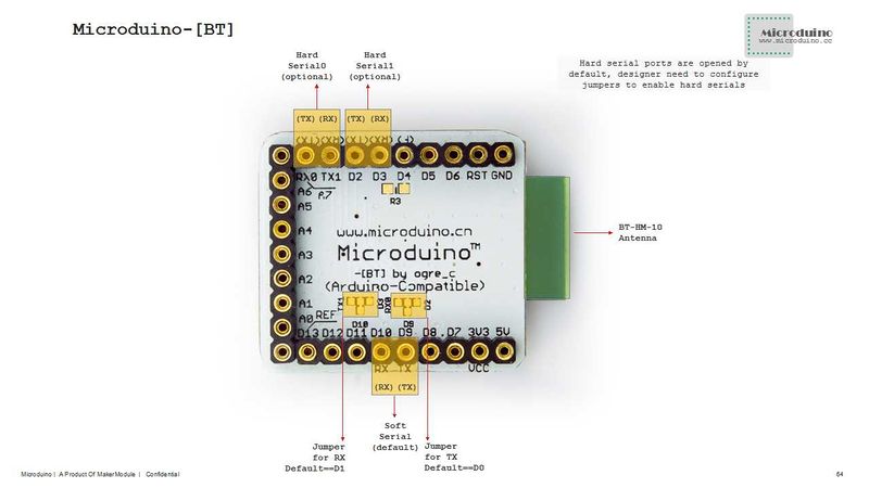
  • If you want to change the jumper cables to meet your requirement, you need to cut the connection between two intermediate of the pad and RX0/TX1, and then connect them to D2, D3(or D9、D10).
    • If it needs to change the jumper, you can change the serial connection of Microduino Shield BT4.0 and Microduino Core from "TX-RX0、RX-TX1" to:
      • TX-D2、RX-D3 (For Core+'s Serial1)
      • TX-D9、RX-D10 (you can adopt SoftwareSeria libray to solve the problem)

Pin description

Microduino-BT


Microduino-BT


HM-10 Pin Microduino Pin Function
TX RX0(orD2/D9) It serves as the serial transmission pin (TTL),capable of connecting the RXD of a microcontroller
RX TX1(orD3/D10) It serves as the serial receiving pin (TTL),capable of connecting the TXD of a microcontroller


Application

Download progrm

Program test:File:BLE debug uart1.zip,File:BLE LightBlue time.zip

Shield BT4.0 pass-through data to IOS devices

  • Prepared hardware:Microduino FT232R, Microduino Core, Microduino Shield BT4.0, supported Bluetooth 4.0 devices (iPhone4s upper,iPod touch 5 upper,iPad 3 upper,iPad mini upper);
  • Prepared software: Arduino IDE (version 1.0 or higher), Microduino test program (Arduino part) and LightBlue downloaded from App Store;
  • Start Arduino IED,open the Microduino test program, select board "Microduino Core (Atmega328P@16M,5V)" and then download directly;
  • Start to set the IOS device:
    • start Bluetooth on IOS device;
    • Open LightBlue;
    • Find the "HMSoft" in "Central" tab , then set "Service"-"Characteristics" in order;
    • You can see the debugging window and then click the "Start Notify".
  • ASCII data can be seen to be displayed: "BLE, Time: xxx". Besides, xxx shows the runtime of Microduino-Core and Shield BT4.0's in seconds.

Use Core32u4 to debug Shield BT4.0

  • Hardware needed:Microduino FT232R,Microduino Core 32u4 and Microduino Shield BT4.0;
  • Software needed:Arduino IDE(version 1.0 or higher), Microduino test program(Arduino part);
    • (You can keep the current jumper(RXO,TX1) without change for Microduino-CoreUSb utilizes USB simulation port 0(Serial) and the RXO and TX1 of Microduino-BT are the serial1 of Microduino-CoreUSB;
  • Start Arduino IED, open Microduino test program, select Microduino-CoreUSB and then download;
  • Check whether the serial communication is ok:
    • Send the capitalized "AT"(NO \r\n after it) after opening the corresponding serial monitor. And if the return shows "OK", it means the setup is successful.

Use Core+'s uart1 to debug Shield BT4.0

  • Hardware needed:Microduino FT232R, Microduino Core+ and Microduino Shield BT4.0;
  • Software needed:Arduino IDE (version 1.0 or higher), Microduino test program (Arduino part);
  • Other condition:The player has changed the jumper, making the serial changed to D2、D3;
  • Start Arduino IED, open Microduino test program, select the board type "Microduino Core (Atmega328P@16M,5V)" and then download directly;
  • Check the serial communication:
    • Open the serial monitor,send the capitalized “AT”( without \r\n behind), if the return shows“OK”,that means a successful configuration.

How to Connect Two Microduino-BT Modules

  • You need to use AT instruction to set up some parameters via the serial port. So you can refer to the following module handbook:

File:Bluetooth40 en.pdf

  • Module Needed
Related Hardware Number Function
Microduino-BT 2 For communication connection
Microduino-USBTTL 1 For serial port communication debugging
Dupont line 4 For circuit connection
USB cable 2 For power supply
  • We must set one module as the master machine and another as the slave machine. The master machine will search the requirement of the slave machine and then match them. When we start to build the hardware and connect Microduino-BT and Microduino-USBTTL, we need to connect four wires:
Microduino-BT Microduino-USBTTL
RX0 TX1
TX1 RX0
3V3 3V3
GND GND
BT-USBTTL-1.jpg
  • Slave Machine Parameter Configuration:
    • Build the circuit according to the schematic and supply the power through USB cable;
    • Open Arduino editor, choose the right COM port, open the serial port debugging, or you can use other Com debug assistant.
    • First, choose the serial port baud rate as 9600 , set the mode as “No line terminator”. Click “send” or “enter” after inputting “AT” in the serial port data sending box, you’ll receive “OK” at the data receiving end, meaning your BT module can be set via AT instruction.

Notice: If there is no return value, you need to change the baud rate to 115200. It is probably the unmatched baud rate that leads to failed communication. Baud rate setup can refer to the module handbook above.

    • Check and set a BT module under slave mode(The default is the slave mode):
      • Click “send” or “enter” after inputting “AT+ROLE” in the serial port sending box, you can set it under the slave mode if it returns as “OK+Get0” and under the host mode if it returns as “OK+Get1”. So, you need to set the slave mode via “AT+ROLE0” instruction.
    • Check the work type of the slave machine--“Power to work instantly”.
      • Click “send” or “enter” after inputting “AT+IMME?” in the serial port data sending box, you can know that “Power to work instantly” if it returns as “OK=Get1”. Otherwise, you need to set it as “Power to work instantly” mode via “AT+IMME?” instruction. After finishing configuring the slave machine parameter, you just need to get it powered.
  • Master Machine Parameter Configuration:
    • Check and set another BT module to be under the master machine mode:
      • Click “send” or “enter” after inputting “AT+ROLE?” in the serial port data sending box. If it returns to be “OK+Get0”, then it is under the slave mode. You need to set it under the host mode through “AT+ROLE1” instruction. Generally, by this time you can get your Bluetooth connected. The host machine will search the slave devices and connect them automatically.


    • If it fails to connect, please check whether the work type of the host machine is “Power to wait ” (Default).
      • Click “send” or “enter” after inputting “AT+IMME?” in the serial port data sending box. If it returns to be “OK+ Get1, then it is under the mode of “Power to work instantly”. So, you need to set it under the mode of “Power to wait” through “AT+IMME0” instruction.
    • If it still can’t connect under the mode of “Power to wait”, it is probably the host machine has connected other Bluetooth devices.(Since it will try to connect the preserved slave devices instantly, this may lead to disconnection with the existing devices.) So, you can use “AT+CLEAR” to clear the originally stored connection information. In this way, it can enter the search state and search once again for device and then connect.
    • If it still can not be connected, you can try to connect devices in the fixed Bluetooth MAC address
    • Connect Microduino-USBTTL with the slave machine, configure the host machine, check MAC address of the slave machine and save the address.
      • Click “send” or “enter” after inputting “AT+ADDR?” in the serial port data sending box. If it returns to be address “OK+ADDR:MAC(XXX)”, please don’t forget the address since the host machine needs to make connection through the address. After configuring the slave parameter, the only thing you need is to get it charged.
      • Connect Microduino-USBTTL and the host machine, configure the host machine, set the work type of the host--”Power to work instantly”.
      • Just input “AT+CONXXX” in the serial port data sending box. “XXX” is the MAC address you keep in mind. Then, click “send” or “enter”. If it returns to be “OK”, it means a successful connection and you can see two Bluetooth indicators don’t blink. It it can’t connect to the fixed devices, it’ll enter the state of search and at this time, you can try “AT+RESET” to restart the module and reconnect.
    • After it is connected, if you cut off the device, you can’t reconnect it once again. You need to restart the serial monitor, set the work type of the host machine--”Power to wait”. Thus, you can get it connected every time it gets powered off.

Note:If you use Android device to debug, you need to make sure the system should be version 4.3 or higher so that Microduino-BT can be detected.

A simple test of Microduino-Shield BT4.0

FQA

  • This module can’t make pair with win7?
    • Check the BT version in win7, this module only support BLE 4.0 version and default password is 000000.
  • Does this module can reset by button?
    • No, it can be reset by power down.
  • This module can’t make pair with iphone and Android phone?
    • This issue mostly is caused by the BT version. This module only supports BT4.0 protocol.
    • For Andriod OS: 4.3 release
    • For IOS: iPhone4s upper, iPod touch 5 upper, iPad 3 upper and iPad mini upper

Buy

History

  • On June 5, 2013, the second time proofing is completed, changed its name to the "Microduino - (BT)" and added the third optional serial port - UART1, divided into 2 version, version 2.1, a module used for HM09;A 4.0 version, module used for HM10.
  • On May 10, 2013, the board is completed.

Pictures

Microduino BT 4.0 Front
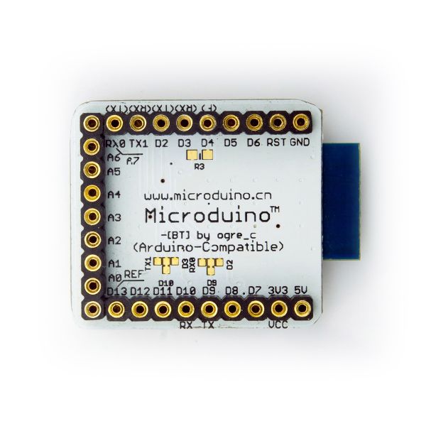
Microduino BT 4.0 Back

Video