Difference between revisions of "Joystick Lantern"
From Microduino Wiki
(Created page with "{{Language| Joystick lantern}} {| style="width: 800px;" |- | ==Objective== To control the lantern's color and brightness through Joystick. ==Principle== ==Equipment== {|cla...") |
|||
| Line 1: | Line 1: | ||
| − | {{Language| Joystick | + | {{Language| Joystick Lantern}} |
{| style="width: 800px;" | {| style="width: 800px;" | ||
|- | |- | ||
| | | | ||
==Objective== | ==Objective== | ||
| − | To control the lantern's color and brightness through Joystick. | + | To control the lantern's color and brightness through Joystick. |
==Principle== | ==Principle== | ||
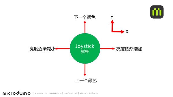
| + | Here we use Joystick detect the status of the rocker, judge the direction, and control the color and brightness of the LED light. | ||
| + | [[File: Joystick_colorled-sch.jpg|600px|center]] | ||
==Equipment== | ==Equipment== | ||
| Line 17: | Line 19: | ||
|[[Microduino-Sensorhub]]||1||Sensor pin board | |[[Microduino-Sensorhub]]||1||Sensor pin board | ||
|- | |- | ||
| − | | [[Microduino- | + | | [[Microduino-Color LED]]||1||Colored light |
|- | |- | ||
| [[Microduino-Joystick]]||1||Joystick sensor | | [[Microduino-Joystick]]||1||Joystick sensor | ||
| Line 24: | Line 26: | ||
|} | |} | ||
[[File: Joystick_colorled.jpg|600px|center|thumb]] | [[File: Joystick_colorled.jpg|600px|center|thumb]] | ||
| + | ==Preparation== | ||
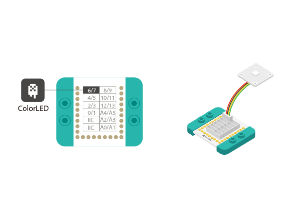
| + | *Setup 1:Connect the '''IN''' on the back of the Color LED to the D6 digital port of the Hub. (D6 is the pin to control LED, which can be customized by used. ) | ||
| + | [[file:mCookie-strandtext-sensor.JPG|600px|center]] | ||
| + | *Setup 2:Then, connect the Joystick to A0/A1 interface. | ||
| + | [[file:mCookie-Joystick-led-sensor.JPG|600px|center]] | ||
| + | *Setup 3:Stack the CoreUSB, Hub, Color led and Joystick together and then connect them to the computer with a USB cable. | ||
| + | [[file:mCookie-Joystick led-pc.JPG|600px|center]] | ||
| + | ==Debugging == | ||
| + | *Open Arduino IDE and copy the following code into IDE. | ||
| + | <source lang="cpp"> | ||
| + | #include <Adafruit_NeoPixel.h> | ||
| + | #define PIN 6 | ||
| + | Adafruit_NeoPixel strip = Adafruit_NeoPixel(6, PIN, NEO_GRB + NEO_KHZ800); | ||
| + | |||
| + | uint32_t color_m[9][3] = | ||
| + | { | ||
| + | {0, 255, 255}, | ||
| + | {255, 0, 0}, | ||
| + | {248, 141, 30}, | ||
| + | {255, 255, 0}, | ||
| + | {0, 255, 0}, | ||
| + | {0, 127, 255}, | ||
| + | {0, 0, 255}, | ||
| + | {139, 0, 255}, | ||
| + | {255, 255, 255} | ||
| + | }; | ||
| + | uint32_t color[9] = | ||
| + | { | ||
| + | strip.Color(0, 0, 0), strip.Color(255, 0, 0), strip.Color(248, 141, 30), strip.Color(255, 255, 0), strip.Color(0, 255, 0), strip.Color(0, 127, 255), strip.Color(0, 0, 255), strip.Color(139, 0, 255), strip.Color(255, 255, 255) | ||
| + | }; | ||
| − | + | #define JoystickX_PIN A1 | |
| − | + | #define JoystickY_PIN A0 | |
| − | |||
| − | |||
| − | |||
| − | |||
| − | |||
| − | |||
| − | == | + | int sensorValueX, sensorValueY; |
| − | Code Description | + | |
| − | * | + | int num, color_l; |
| − | *Joystick | + | |
| + | #define val_max 255 | ||
| + | #define val_min 0 | ||
| + | |||
| + | void setup() { | ||
| + | // put your setup code here, to run once: | ||
| + | Serial.begin(9600); | ||
| + | strip.begin(); | ||
| + | strip.show(); // Initialize all pixels to 'off' | ||
| + | |||
| + | pinMode(JoystickX_PIN, INPUT); | ||
| + | pinMode(JoystickY_PIN, INPUT); | ||
| + | |||
| + | for (int i = 0; i < 9; i++) | ||
| + | { | ||
| + | colorWipe(color[i]); | ||
| + | delay(300); | ||
| + | } | ||
| + | |||
| + | colorWipe(color[0]); | ||
| + | } | ||
| + | |||
| + | void loop() { | ||
| + | // put your main code here, to run repeatedly: | ||
| + | sensorValueX = analogRead(JoystickX_PIN); | ||
| + | sensorValueY = analogRead(JoystickY_PIN); | ||
| + | |||
| + | if (sensorValueY <= 10) | ||
| + | { | ||
| + | delay(500); | ||
| + | num++; | ||
| + | if (num > 8) | ||
| + | num = 0; | ||
| + | } | ||
| + | else if (sensorValueY > 800) | ||
| + | { | ||
| + | delay(500); | ||
| + | num--; | ||
| + | if (num < 0) | ||
| + | num = 8; | ||
| + | } | ||
| + | |||
| + | if (sensorValueX <= 10) | ||
| + | { | ||
| + | delay(10); | ||
| + | color_l++; | ||
| + | if (color_l > 255) | ||
| + | color_l = 255; | ||
| + | } | ||
| + | else if (sensorValueX > 800) | ||
| + | { | ||
| + | delay(10); | ||
| + | color_l--; | ||
| + | if (color_l < 0) | ||
| + | color_l = 0; | ||
| + | } | ||
| + | |||
| + | colorWipe(strip.Color(map(color_l, val_min, val_max, 0, color_m[num][0]), map(color_l, val_min, val_max, 0, color_m[num][1]), map(color_l, val_min, val_max, 0, color_m[num][2]))); | ||
| + | /* | ||
| + | Serial.print(num); | ||
| + | Serial.print("\t"); | ||
| + | Serial.println(color_l); | ||
| + | */ | ||
| + | } | ||
| + | |||
| + | void colorWipe(uint32_t c) { | ||
| + | for (uint16_t i = 0; i < strip.numPixels(); i++) { | ||
| + | strip.setPixelColor(i, c); | ||
| + | strip.show(); | ||
| + | } | ||
| + | } | ||
| + | </source> | ||
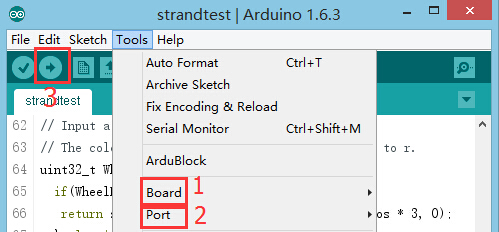
| + | * Choose the right board and COM port, compile and download. | ||
| + | [[file:upload.JPG|thumb|800px|center]] | ||
| + | ==Code Description== | ||
| + | * Pre-set color: " color_m[9][3"; Currently, there are nine colors, which can be changed by users. The number of color needs to correspond to array. For example, if you add two colors, they needs to changed to " color_m[11][3]" correspondingly. | ||
| + | *Definition of the Joystick control pin: | ||
<source lang="cpp"> | <source lang="cpp"> | ||
#define JoystickX_PIN A1 | #define JoystickX_PIN A1 | ||
#define JoystickY_PIN A0 | #define JoystickY_PIN A0 | ||
</source> | </source> | ||
| − | * | + | *Color selection in the X-axis direction |
| − | + | <source lang="cpp"> | |
if (sensorValueY <= 10) | if (sensorValueY <= 10) | ||
{ | { | ||
| Line 59: | Line 161: | ||
} | } | ||
</source> | </source> | ||
| − | * | + | *Brightness selection in the Y-axis direction. |
<source lang="cpp"> | <source lang="cpp"> | ||
if (sensorValueX <= 10) | if (sensorValueX <= 10) | ||
| Line 76: | Line 178: | ||
} | } | ||
</source> | </source> | ||
| − | * | + | *Colored LED display |
<source lang="cpp"> | <source lang="cpp"> | ||
colorWipe(strip.Color(map(color_l, val_min, val_max, 0, color_m[num][0]), map(color_l, val_min, val_max, 0, color_m[num][1]), map(color_l, val_min, val_max, 0, color_m[num][2]))); | colorWipe(strip.Color(map(color_l, val_min, val_max, 0, color_m[num][0]), map(color_l, val_min, val_max, 0, color_m[num][1]), map(color_l, val_min, val_max, 0, color_m[num][2]))); | ||
</source> | </source> | ||
| − | |||
==Result== | ==Result== | ||
| − | + | Toggle the Joystick in the X-axis direction to choose color of the LED light and in the Y-axis to select brightness. | |
| − | |||
==Video== | ==Video== | ||
|} | |} | ||
Latest revision as of 09:16, 6 November 2015
| Language: | English • 中文 |
|---|
ContentsObjectiveTo control the lantern's color and brightness through Joystick. PrincipleHere we use Joystick detect the status of the rocker, judge the direction, and control the color and brightness of the LED light. Equipment
Preparation
Debugging
#include <Adafruit_NeoPixel.h>
#define PIN 6
Adafruit_NeoPixel strip = Adafruit_NeoPixel(6, PIN, NEO_GRB + NEO_KHZ800);

uint32_t color_m[9][3] =
{
  {0, 255, 255},
  {255, 0, 0},
  {248, 141, 30},
  {255, 255, 0},
  {0, 255, 0},
  {0, 127, 255},
  {0, 0, 255},
  {139, 0, 255},
  {255, 255, 255}
};
uint32_t color[9] =
{
  strip.Color(0, 0, 0), strip.Color(255, 0, 0), strip.Color(248, 141, 30), strip.Color(255, 255, 0), strip.Color(0, 255, 0), strip.Color(0, 127, 255), strip.Color(0, 0, 255), strip.Color(139, 0, 255), strip.Color(255, 255, 255)
};

#define JoystickX_PIN A1
#define JoystickY_PIN A0

int sensorValueX, sensorValueY;

int num, color_l;

#define val_max 255
#define val_min 0

void setup() {
  // put your setup code here, to run once:
  Serial.begin(9600);
  strip.begin();
  strip.show(); // Initialize all pixels to 'off'

  pinMode(JoystickX_PIN, INPUT);
  pinMode(JoystickY_PIN, INPUT);

  for (int i = 0; i < 9; i++)
  {
    colorWipe(color[i]);
    delay(300);
  }

  colorWipe(color[0]);
}

void loop() {
  // put your main code here, to run repeatedly:
  sensorValueX = analogRead(JoystickX_PIN);
  sensorValueY = analogRead(JoystickY_PIN);

  if (sensorValueY <= 10)
  {
    delay(500);
    num++;
    if (num > 8)
      num = 0;
  }
  else if (sensorValueY > 800)
  {
    delay(500);
    num--;
    if (num < 0)
      num = 8;
  }

  if (sensorValueX <= 10)
  {
    delay(10);
    color_l++;
    if (color_l > 255)
      color_l = 255;
  }
  else if (sensorValueX > 800)
  {
    delay(10);
    color_l--;
    if (color_l < 0)
      color_l = 0;
  }

  colorWipe(strip.Color(map(color_l, val_min, val_max, 0, color_m[num][0]), map(color_l, val_min, val_max, 0, color_m[num][1]), map(color_l, val_min, val_max, 0, color_m[num][2])));
  /*
    Serial.print(num);
    Serial.print("\t");
    Serial.println(color_l);
    */
}

void colorWipe(uint32_t c) {
  for (uint16_t i = 0; i < strip.numPixels(); i++) {
    strip.setPixelColor(i, c);
    strip.show();
  }
}
Code Description
#define JoystickX_PIN A1
#define JoystickY_PIN A0
	  if (sensorValueY <= 10)
  {
    delay(500);
    num++;
    if (num > 8)
      num = 0;
  }
  else if (sensorValueY > 800)
  {
    delay(500);
    num--;
    if (num < 0)
      num = 8;
  }
if (sensorValueX <= 10)
  {
    delay(10);
    color_l++;
    if (color_l > 255)
      color_l = 255;
  }
  else if (sensorValueX > 800)
  {
    delay(10);
    color_l--;
    if (color_l < 0)
      color_l = 0;
  }
colorWipe(strip.Color(map(color_l, val_min, val_max, 0, color_m[num][0]), map(color_l, val_min, val_max, 0, color_m[num][1]), map(color_l, val_min, val_max, 0, color_m[num][2])));ResultToggle the Joystick in the X-axis direction to choose color of the LED light and in the Y-axis to select brightness. Video |


