Difference between revisions of "The Use of DC Motor"
From Microduino Wiki
(Created page with " {| style="width: 800px;" |- | ==Outline== N20 direct current speed reduction motor: Compared with the ordinary DC motor, it is equipped with gear speed reduction box, which o...") |
|||
| Line 32: | Line 32: | ||
=== Wire Connection of DC Motor === | === Wire Connection of DC Motor === | ||
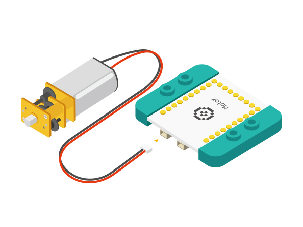
| − | *Connect a DC motor to ( | + | *Connect a DC motor to (OUT1A, OUT1B) and the other motor to (OUT2A, OUT2B); |
*DC motor control pin: | *DC motor control pin: | ||
<source lang="cpp"> | <source lang="cpp"> | ||
| Line 43: | Line 43: | ||
</source> | </source> | ||
===Preparation | ===Preparation | ||
| − | *Setup | + | *Setup 1: Connect a motor to the Motor module as the diagram showed above; |
[[File: _304_DozingDonkey _Motor.jpg|600px|center]] | [[File: _304_DozingDonkey _Motor.jpg|600px|center]] | ||
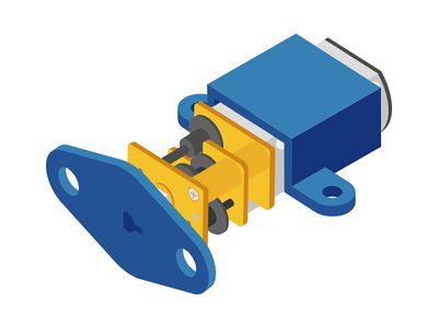
| − | *Setup | + | *Setup 2: You can install accessories in the motor and the axis according to project needs, and then fix them on other materials. |
[[File: _304_DozingDonkey _Motor1.jpg|400px|center]] | [[File: _304_DozingDonkey _Motor1.jpg|400px|center]] | ||
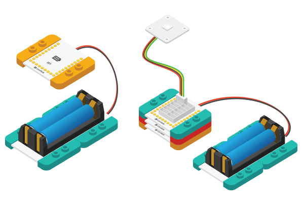
| − | *Setup | + | *Setup 3: Connect the activated battery box with BM module. |
[[File:CoreUSB_Ble_steup2.jpg|600px|center]] | [[File:CoreUSB_Ble_steup2.jpg|600px|center]] | ||
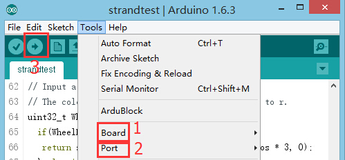
| − | *Setup | + | *Setup 4: Connect all devices to a computer with a USB cable. |
[[file:mCookie-n20-pc.JPG|600px|center]] | [[file:mCookie-n20-pc.JPG|600px|center]] | ||
| Line 121: | Line 121: | ||
* Open Arduino IDE and copy the following codes to IDE. | * Open Arduino IDE and copy the following codes to IDE. | ||
<source lang="cpp"> | <source lang="cpp"> | ||
| − | //( | + | //( D6, D8) controls motor (1A, 1B) |
#define OUT1A 6 | #define OUT1A 6 | ||
#define OUT1B 8 | #define OUT1B 8 | ||
| − | //( | + | //( D5, D7) controls motor (2A, 2B) |
#define OUT2A 5 | #define OUT2A 5 | ||
#define OUT2B 7 | #define OUT2B 7 | ||
Revision as of 06:46, 30 September 2016
ContentsOutlineN20 direct current speed reduction motor: Compared with the ordinary DC motor, it is equipped with gear speed reduction box, which offers lower rotation rate and larger torque, enhancing the use rate of the DC motor in the automation industry. SpecificationSpeed Reduction DC Motor
DevelopmentEquipment
Wire Connection of DC Motor
//(D6,D8) controls (1A,1B) motor
#define OUT1A 6
#define OUT1B 8
//(D5,D7) controls (2A,2B) motor
#define OUT2A
#define OUT2B 7
===Preparation
Experiment 1: Connection and disconnection control
#define OUT1A 6
#define OUT1B 8
#define OUT2A 5
#define OUT2B 7

void setup()
{
  pinMode(OUT1A, OUTPUT);
  pinMode(OUT1B, OUTPUT);
  pinMode(OUT2A, OUTPUT);
  pinMode(OUT2B, OUTPUT);
}

void loop()
{
head();
delay(2000);
back();
delay(1000);
stop();
delay(500);
}

void head()
{
  digitalWrite(OUT1A, HIGH);
  digitalWrite(OUT1B, LOW);
  digitalWrite(OUT2A, HIGH);
  digitalWrite(OUT2B, LOW);
}
void back()
{
  digitalWrite(OUT1A, LOW);
  digitalWrite(OUT1B, HIGH);
  digitalWrite(OUT2A, LOW);
  digitalWrite(OUT2B, HIGH);
}
void stop()
{
  digitalWrite(OUT1A, LOW);
  digitalWrite(OUT1B, LOW);
  digitalWrite(OUT2A, LOW);
  digitalWrite(OUT2B, LOW);
}
=Debugging
Experiment 2: PWM Motor Speed Control
//( D6, D8) controls motor (1A, 1B)
#define OUT1A 6
#define OUT1B 8
//( D5, D7) controls motor (2A, 2B)
#define OUT2A 5
#define OUT2B 7

void setup()
{
  pinMode(OUT1A, OUTPUT);
  pinMode(OUT1B, OUTPUT);
  pinMode(OUT2A, OUTPUT);
  pinMode(OUT2B, OUTPUT);
}

void loop()
{
  for (int fadeValue = 0; fadeValue <= 255; fadeValue += 5)
    //Loop statement. Along with PWM rate increases, you can change brightness level by controlling fadeValue.
  {
    analogWrite(OUT1A, fadeValue);  //Write rate level into the motor
    digitalWrite(OUT1B, LOW);
    analogWrite(OUT2A, fadeValue);
    digitalWrite(OUT2B, LOW);
    delay(100);                       //Delay time of rate. (The unit is ms)
  }
  for (int fadeValue = 255; fadeValue >= 0; fadeValue -= 5)
    // Loop statement. Along with PWM rate decreases, you can change brightness level by controlling fadeValue.
  {
    digitalWrite(OUT1A, LOW);
    analogWrite(OUT1B, fadeValue);  // Write rate level into the motor
    digitalWrite(OUT2A, LOW);
    analogWrite(OUT2B, fadeValue);
    delay(100);                     // Delay time of rate. (The unit is ms)
  }
  delay(1000);
}
Program Debugging
Video |


