Difference between revisions of "Microduino NRF communication-201KIT"
From Microduino Wiki
(Created page with "{| style="width: 800px;" |- | ==概述== *项目名称:Microduino nrf24通讯 *目的:通过microduino nrf24模块对led灯进行无线控制。结合按键控制led灯的...") |
|||
| Line 2: | Line 2: | ||
|- | |- | ||
| | | | ||
| − | == | + | ==Outline== |
| − | * | + | *Project:Microduino nrf24 communication |
| − | * | + | *Objective:Use the microduino nrf24 module to wireless conrotl LED and use the button to control LED on or off. |
| − | * | + | *Difficulty:Elementary |
| − | * | + | *Time-consuming:Half an hour |
| − | * | + | *Maker:Microduino Studio-YLB |
| − | == | + | ==Bill of Materials== |
| − | * | + | *Microduino equipment |
{|class="wikitable" | {|class="wikitable" | ||
|- | |- | ||
| − | | | + | |Module||Number||Function |
|- | |- | ||
| − | |Microduino-Core+||1|| | + | |Microduino-Core+||1||Master,send the control signal (You can use Microduino-Core too) |
|- | |- | ||
| − | |Microduino-Core||1|| | + | |Microduino-Core||1||Slave,receive the control signal |
|- | |- | ||
| − | |Microduino-FT232R ||1|| | + | |Microduino-FT232R ||1||Download program |
|- | |- | ||
| − | |Microduino-nRF24||2|| | + | |Microduino-nRF24||2||Wireless communication |
|} | |} | ||
| − | * | + | *Other equipment |
{|class="wikitable" | {|class="wikitable" | ||
|- | |- | ||
| − | | | + | |Button||1||Function selection |
|- | |- | ||
| − | | | + | |LED||1||Display communication state |
|- | |- | ||
| − | | | + | |bread board||1||Set up circuit |
|- | |- | ||
| − | | | + | |Jumper||1||connect the circuit |
|} | |} | ||
| − | * | + | *Module |
| − | + | In order to facilitate debugging, reduce the height of module combination, add the extension board Microduino Duo-V. | |
| + | |||
[[File:201KIT.jpg|600px|center|thumb|201KIT图片]] | [[File:201KIT.jpg|600px|center|thumb|201KIT图片]] | ||
| − | == | + | ==Document== |
| − | == | + | ==Debugging== |
|- | |- | ||
| | | | ||
| − | * | + | *Step 1:Set up system |
|- | |- | ||
| | | | ||
| − | + | Prepare master module: | |
| − | Microduino-Core+ | + | Microduino-Core+, Microduino-FT232R, Microduino-nRF24, button, bread board |
|- | |- | ||
| | | | ||
| − | + | Prepare slave module: | |
| − | Microduino-Core | + | Microduino-Core, Microduino-NRF24,Microduino Duo-V, LED |
|- | |- | ||
| | | | ||
| − | * | + | *Setp 2:Set up button |
| − | + | Button connection:use internal pull up, set it in program by yourself. | |
[[File:201KIT-button.jpg|600px|center|thumb|201KIT-button图片]] | [[File:201KIT-button.jpg|600px|center|thumb|201KIT-button图片]] | ||
| Line 61: | Line 62: | ||
|- | |- | ||
| | | | ||
| − | + | The whole systme picture: | |
[[File:201KIT-ok.jpg|600px|center|thumb|201KIT]] | [[File:201KIT-ok.jpg|600px|center|thumb|201KIT]] | ||
|- | |- | ||
| | | | ||
| − | * | + | *Setp 3:Download the example program |
| − | + | download the program: | |
|- | |- | ||
| | | | ||
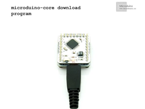
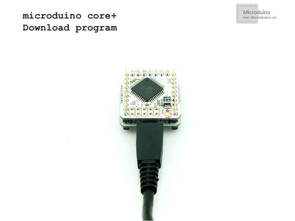
| − | + | Choose "Microduino Core +(Atmega644P@16M,5V)" on master, and choose "Microduino Core (Atmega328P@16M,5V)" on slave, download directly. | |
| + | |||
[[File:download-core.jpg|600px|center|thumb|download-core]] | [[File:download-core.jpg|600px|center|thumb|download-core]] | ||
[[File:download-core+.jpg|600px|center|thumb|download-core+]] | [[File:download-core+.jpg|600px|center|thumb|download-core+]] | ||
| − | == | + | ==Result== |
| − | + | Download the program to core board, press the button on master to contorl the LED on slave, light and off in turn. | |
| + | |||
| − | == | + | ==Note== |
| − | * | + | *The parameters should be match in NRF's communication function of sending and receiving. |
| − | * | + | *The button use the internal pull up which need to define in program. |
|} | |} | ||
Revision as of 07:59, 22 February 2014
Outline
Bill of Materials
In order to facilitate debugging, reduce the height of module combination, add the extension board Microduino Duo-V. File:201KIT.jpg 201KIT图片 DocumentDebugging | |||||||||||||||||||||||||||
| |||||||||||||||||||||||||||
|
Prepare master module: Microduino-Core+, Microduino-FT232R, Microduino-nRF24, button, bread board | |||||||||||||||||||||||||||
|
Prepare slave module: Microduino-Core, Microduino-NRF24,Microduino Duo-V, LED | |||||||||||||||||||||||||||
Button connection:use internal pull up, set it in program by yourself. | |||||||||||||||||||||||||||
|
The whole systme picture: File:201KIT-ok.jpg 201KIT | |||||||||||||||||||||||||||
download the program: | |||||||||||||||||||||||||||
|
Choose "Microduino Core +(Atmega644P@16M,5V)" on master, and choose "Microduino Core (Atmega328P@16M,5V)" on slave, download directly. ResultDownload the program to core board, press the button on master to contorl the LED on slave, light and off in turn.
Note
|


