|
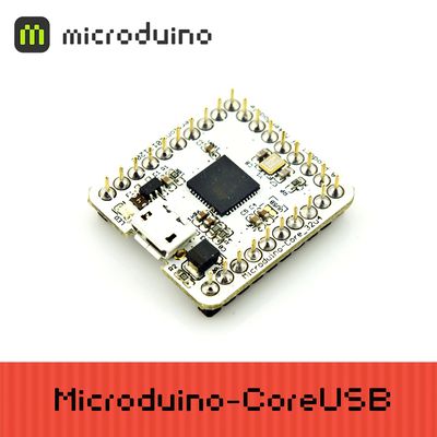
Microduino-CoreUSB 8-bit microcontroller development board with the ATMEGA32U4 series as the core,and it is a open-source controller module compatible with Arduino Leonardo.
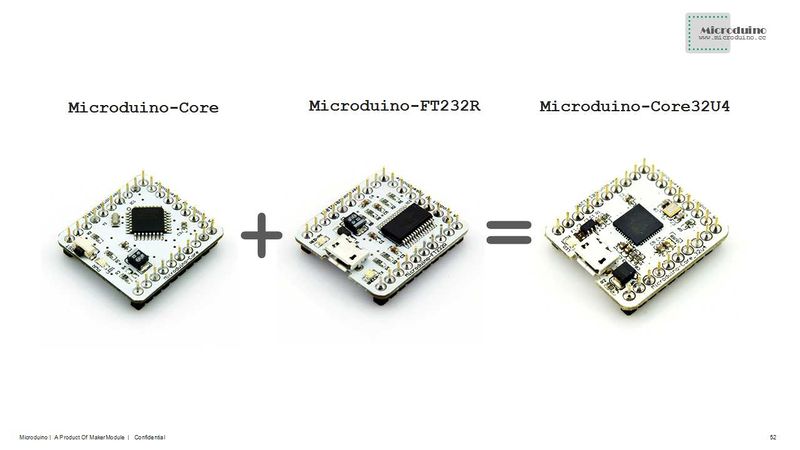
The difference between Microduino-CoreUSB and Microduino-core and Microduino-core+ is that the Microduino-CoreUSB contains a microcontroller and USB communication, equivalent to (Microduino-core + Microduino-USBTTL), and its pins conform to the microduino specification.
Microduino uses java , the development environment of C language, same with Arduino. Players can use Arduino IDE, cooperating with software such as Flash or Processing , with Microduino and other electronic components,modules and sensors to make many funny interactive works.
Features
- It contains microcontroller and USB communication, so you can directly download programs through the USB port, having no more need of Microduino-USBTTL;
- USB overcurrent protection;
- Small, cheap, stackable, and open;
- Open-source hardware circuit design, and programming development environment compatible with Arduino ;
- Same with Arduino, Microduino can use ISP download way, to program to「bootloader」 flexibly;
- Unified Microduino interface specification, and abundant peripheral modules, can be connected and extended quickly, conveniently, and flexibly with other modules and sensors conforming to the Microduino interface specification;
- 2.54 spacing Female Header interface is convenient to integrate into the hole plate.
Specification
| Flash |
32 KB(ATMEGA32U4). 4 KB during it is used to guide the program.
|
| SRAM |
2.5 KB(ATMEGA32U4)
|
| EEPROM |
1 KB(ATMEGA32U4)
|
| Clock speed |
16 MHz
|
- Digital I/O There are 22 digital input/output terminals:
- Labeled on the module of D0~D13, and A0~A7.
- Analog I/O There are 10 analog input/output:
- Labeled on thee module of A0,A1,A2,A3,A6,A7,D8(A8),D9(A9),D3(A10) and D4(A11);
- Each offers a 10-bit resolution( that is 0~1024). By default, the measurement range of the analog voltage is the value from GND to VCC;
- Please refer toanalogRead() function.
- PWM support. There are 8:
- Labeled on the module of respectively SCL,D3,D4,D5,D6,D7,D8 and D9.
- Please refer toanalogWrite() function.
- Serial port support. There are 2:
- USB virtual serial port Serial;
- Labeled on the module of Serial1[D0(RX),D1(TX)]。
- SPI support. There is one:
- Labeled on the module of D13(SCK),D12(MISO),D11(MOSI),D10(SS).
- I2C support. There is one:
- Labeled on the module of SDA(D18),SCL(D19).
- External interrupt support. There are 5:
- Labeled on the module of SCL(interrupt0), SDA(interrupt1), D0(interrupt2), D1(interrupt3), and D2(interrupt4).
- Please refer toattachInterrupt() function.
- Support the ISP download function.
- Support AREF end.
| Pin
|
Original Pin Name
|
Map Pin Name
|
Digital Pin
|
Analog Pin
|
interrupt
|
PWM
|
Serial
|
SPI
|
I2C
|
Power
|
| 1 |
VCC |
+5V |
|
|
|
|
|
|
|
+5V
|
| 2 |
VCC |
+3V3 |
|
|
|
|
|
|
|
+3.3V
|
| 3 |
(OC0A/OC1C/#RTS)PB7 |
D7 |
D7 |
|
|
yes |
|
|
|
|
| 4 |
(OC1B/0C4B/ADC13)PB6 |
D8 |
D8 |
A8 |
|
yes |
|
|
|
|
| 5 |
(OC1A/#OC4B/ADC12)PB5 |
D9 |
D9 |
A9 |
|
yes |
|
|
|
|
| 6 |
(SS)PB0 |
D10 |
D10 |
|
|
|
|
SS |
|
|
| 7 |
(PDI/MOSI)PB2 |
D11 |
D11 |
|
|
|
|
MOSI |
|
|
| 8 |
(PDO/MISO)PB3 |
D12 |
D12 |
|
|
|
|
MISO |
|
|
| 9 |
(SCK)PB1 |
D13 |
D13 |
|
|
|
|
SCK |
|
|
| 10 |
AREF |
AREF |
|
|
|
|
|
|
|
|
| 11 |
(ADC7/TDI)PF7 |
A0 |
D14 |
A0 |
|
|
|
|
|
|
| 12 |
(ADC6/TDO)PF6 |
A1 |
D15 |
A1 |
|
|
|
|
|
|
| 13 |
(ADC5/TMS)PF5 |
A2 |
D16 |
A2 |
|
|
|
|
|
|
| 14 |
(ADC4/TCK)PF4 |
A3 |
D17 |
A3 |
|
|
|
|
|
|
| 15 |
(SDA/INT1)PD1 |
SDA |
D18 |
|
1 |
|
|
|
SDA |
|
| 16 |
(OC0B/SCL/INT0)PD0 |
SCL |
D19 |
|
0 |
yes |
|
|
SCL |
|
| 17 |
(ADC1)PF1 |
A6 |
D20 |
A6 |
|
|
|
|
|
|
| 18 |
(ADC0)PF0 |
A7 |
D21 |
A7 |
|
|
|
|
|
|
| 19 |
(RXD1/AIN1/INT2)PD2 |
D0 |
D0 |
|
2 |
|
1(RX) |
|
|
|
| 20 |
(TXD1/INT3)PD3 |
D1 |
D1 |
|
3 |
|
1(TX) |
|
|
|
| 21 |
(INT6/AIN0)PE6 |
D2 |
D2 |
|
4 |
|
|
|
|
|
| 22 |
(T1/#OC4D/ADC9)PD6 |
D3 |
D3 |
A10 |
|
yes |
|
|
|
|
| 23 |
(T0/OC4D/ADC10)PD7 |
D4 |
D4 |
A11 |
|
yes |
|
|
|
|
| 24 |
(OC3A/#OC4A)PC6 |
D5 |
D5 |
|
|
yes |
|
|
|
|
| 25 |
(ICP3/CLK0/OC4A)PC7 |
D6 |
D6 |
|
|
yes |
|
|
|
|
| 26 |
RESET |
RST |
|
|
|
|
|
|
|
|
| 27 |
GND |
GND |
|
|
|
|
|
|
|
GND
|
 Microduino-Core32U4-Pinout 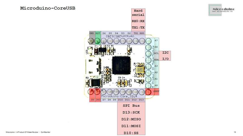 Microduino-Core32U4-Pinout 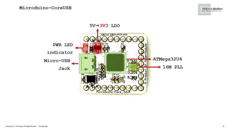 Microduino-Core32U4-Pinout 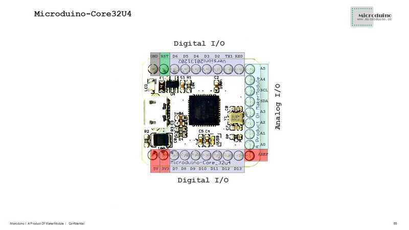 Microduino-Core32U4-Pinout Document
Eagle PCB File:Microduino-core32U4.zip
Development
- 1.Downloading programs to Microduino-CoreUSB , players need to use Microduino-USBTTL module.
- 2.The tutorial of setting the development environment and installing the driver is as following:
- Program Microduino BootLoader
Application
FAQ
- Can this module be used together with Microduino-GPRS/GSM?
Purchase
History
Microduino-Core32U4
Map storage
Frontage
 Microduino-Core32U4 Front Backface
Video
|
