Difference between revisions of "Microduino NRF Controls Household Application"
From Microduino Wiki
(Created page with "{| style="width: 800px;" |- | ==Outline== *Project: Microduino-Nrf24 Controls Household Applications *Purpose: By Microduino-Nrf24 node communication, you can control smart...") |
|||
| Line 68: | Line 68: | ||
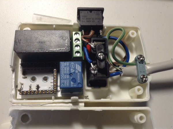
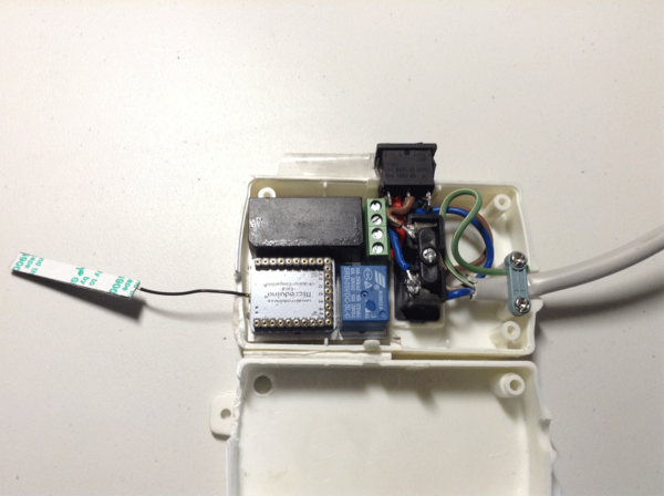
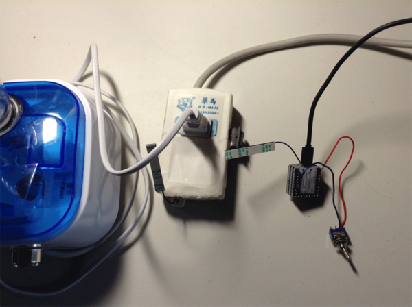
| − | *Step 4: Take off USBTTL module on receiving end, fixate the socket and Microduino module and plug in, making sure offering power for the application to be controlled. Here we adopt a small humidifier. | + | *Step 4: Take off USBTTL module on receiving end, fixate the socket and Microduino module and then plug in, making sure offering power for the application to be controlled. Here we adopt a small humidifier. |
[[File:smartOutletControlNrf243.png|600px|center|thumb]] | [[File:smartOutletControlNrf243.png|600px|center|thumb]] | ||
| Line 77: | Line 77: | ||
==Result== | ==Result== | ||
| − | You can have a control of your household applications | + | You can have a control of your household applications through Microduino-Nrf24. |
==Video== | ==Video== | ||
|} | |} | ||
Latest revision as of 07:21, 31 March 2015
|
Outline
Equipment
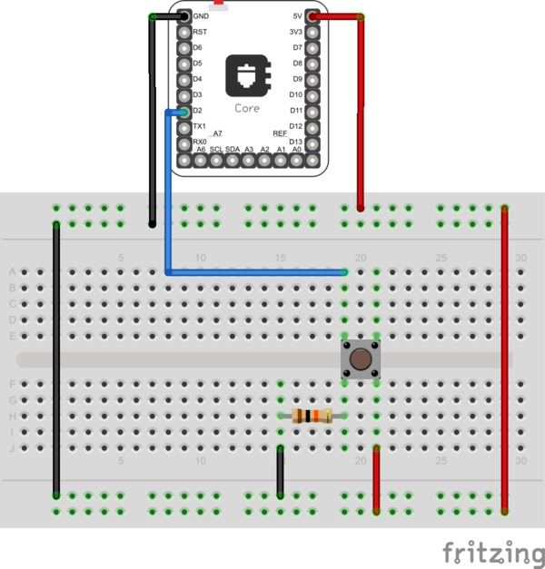
Schematic
ProgramDebugging
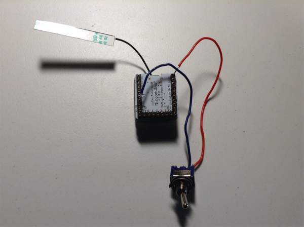
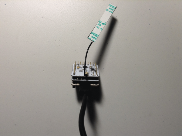
Stack all modules needed. Sender: Receiver:
The side with buttons is the sending end and the other side is receiving end. First, let’s test if the communication is ok. Open serial communication on the receiving end and dial switch, it means OK when the serial port output shows 0,1.
Adjust the switch to smart control mode. ResultYou can have a control of your household applications through Microduino-Nrf24. Video |
