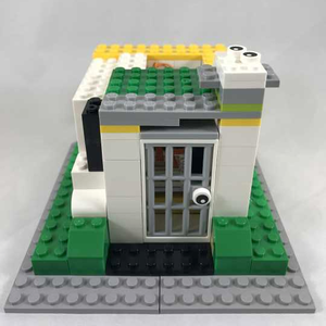
Nightlight Project (X02)
About
This project uses the Light Sensor to detect ambient light and turns on or off the LED Matrix depending how dark it is in the room.
This project was designed for the second generation mCookie Maker kits (102 Basic, 202 Advanced and 302 Expert kits).
Required Materials
- 1 x mCookie Core
- 1 x mCookie USB TTL (102 Kit) or 1 x mBattery (202/302 Kit)
- 1 x mCookie Sensor Hub
- 1 x LED Matrix
- 1 x Light Sensor
- 1 x Touch Button
- 2 x Sensor Cable
- 1 x MicroUSB Cable
Build
NOTE: When connecting sensor wires, push on the plastic connector and not on the wires. Pushing on the wire can damage them.
- Connect the Light Sensor to the Sensor Hub on Pin A2/A3
- Connect the Touch Button to the Sensor Hub on Pin 2/3
- Grab the mCookie USBTTL or mBattery and Stack the mCookie Core on top.
- Stack the mCookie LED Matrix on top of that.
- Stack the mCookie Sensor on top of that.
- Plug in the MicroUSB cable to the mCookie USBTTL or mBattery to a computer.
Program
1. Connect mCookie Core to the PC with the USB Cable. Open the Microduino IDE.
2. Copy and paste the code below and upload.
#include <Adafruit_NeoPixel.h>

const uint8_t LIGHT_SENSOR = A2;      // The pin the Light Sensor is connected to.
const uint8_t TOUCH_SENSOR = 2;       // The pin the Touch Sensor is connected to.

const uint8_t MAX_BRIGHTNESS = 40;    // The Maximum brightness for the LED Module.
const uint8_t BRIGHTNESS_SCALAR = 10; // The value that the brightness increases by each press of the touch sensor.

const uint8_t DEFAULT_BRIGHTNESS = 0; // The default brightness should be less than the Max Brightness.

const int PRESS_DELAY = 1000;         // Time between registering presses from the touch sensor.


#define PIN A0                        // LED CONTROL PIN
#define LED_NUM 6                     // NUMBER OF LEDS CONNECTED

//#define DEBUG

uint8_t current_max = DEFAULT_BRIGHTNESS;
int light_max = 0;                    // Running maximum for light sensor.
bool maxed = false;                   // Will be true the first time the current brightness reaches max brightness.

unsigned long last_press = 0;

// Declaring the 6 LED module object.
Adafruit_NeoPixel strip = Adafruit_NeoPixel(LED_NUM, PIN, NEO_GRB + NEO_KHZ800);

void setup() {
  strip.begin();    // Enabling the 6 LED module.
#ifdef DEBUG
  Serial.begin(9600);
#endif
  pinMode(LIGHT_SENSOR, INPUT);
  pinMode(TOUCH_SENSOR, INPUT);
}

void loop() {
  int light_intensity = analogRead(LIGHT_SENSOR);
  if (light_intensity > light_max)
    light_max = light_intensity;
  // LED brightness changes based on light level.
  int intensity = abs(light_intensity - light_max) * current_max / light_max;
  for (int j = 0; j < LED_NUM; j++)
    strip.setPixelColor(j, strip.Color(intensity, intensity, intensity));
  strip.show();

  // Loop through modes with touch sensor (Increases brightness by 10 up to
  // MAX_BRIGHTNESS and then loops back to off)
  if (!digitalRead(TOUCH_SENSOR) && (millis() - last_press > PRESS_DELAY))
  {
    last_press = millis();
    if (maxed)
    {
      current_max = 0;
      maxed = false;
    }
    else if (!maxed && current_max + BRIGHTNESS_SCALAR == MAX_BRIGHTNESS)
    {
      current_max = MAX_BRIGHTNESS;
      maxed = true;
    }
    else if (current_max + BRIGHTNESS_SCALAR < MAX_BRIGHTNESS)
      current_max += BRIGHTNESS_SCALAR;
    else if (current_max + BRIGHTNESS_SCALAR > MAX_BRIGHTNESS)
    {
      current_max = MAX_BRIGHTNESS;
      maxed = true;
    }
#ifdef DEBUG
    Serial.println("Touch Sensor Read");
    Serial.print("Current Max: ");
    Serial.println(current_max);
#endif
  }

}
3. Select the board, processor and port:
- Go to Tools > Board and select Microduino/mCookie-Core (328p)
- Go to Tools > Processor and select Atmega328P16M,5V
- Go to Tools > Port and select the available port
4. Upload the program by clicking on the right arrow icon on the top left of the window. Or under Sketch > Upload.
NOTE: If not using the default Core module included in the kits, please follow the selecting the board and processor guide.
Debugging
- Open the Serial monitor. Information will print out when the Touch Button has been activated. Also the Current Max brightness value will be printed out.
Tweaking
Variables can be edited to change the threshold / detection value for various functions to better fine tune to your environment.
DEBUG uncomment to debug
PIN is the digital IO pin connected to the NeoPixels (LED Matrix)
LED_NUM is the number of NeoPixels in the LED Matrix
LIGHT_SENSOR is the pin the Light Sensor is connected to.
TOUCH_SENSOR is the pin the Touch Sensor is connected to.
MAX_BRIGHTNESS will change the maximum brightness value. Range between 0 (off) and 255 (blindingly bright). Please be cautious with values above 40.
- Adjustable between 0 ~255
- Default is 40
BRIGHTNESS_SCALAR will change the value that the brightness increases by each press of the touch sensor.
- Default is 10
DEFAULT_BRIGHTNESS will change the default brightness should be less than the Max Brightness. This is how bright the LED Matrix will be at an minimum regardless of the input.
- Adjustable between 0~255 -- should be less than MAX_BRIGHTNESS
- Default is 0 (off)
PRESS_DELAY will change how long between button presses before register another button press to switch between brightness levels. In milliseconds.
- Default is 1000 -- 1 second
Usage
Based on the light level the Light sensor detects. The LED Matrix will turn on accordingly. The darker the room (or if you cover the sensor), the brighter the LED Matrix will shine. 3 brightness levels can be toggled with the touch button with an off mode after maximum brightness mode. Brightness modes will loop around.
