Itty Bitty Buggy: Getting Started (mDesigner)
| mDesigner software installation must be completed before proceeding to this guide.
The mDesigner software installation guide can be found here for Windows / for Mac |
This tutorial will get you getting started with programming Itty Bitty Buggy with mDesigner.
The following topics will be covered:
- Hardware preparation
- Overview of mDesigner's user interface.
- Configuring mDesigner for use with Itty Bitty Buggy.
- Assembling code blocks (creating a program)
- Online vs. Offline Mode
Contents
Hardware Preparation
|
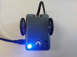
Assemble Itty Bitty Buggy into it's default Buggy mode with mCenter+ on top of Buggy Base. Ensure the cable is connected to pin D2/D3 on mCenter+ and the other end connected to to Buggy Base. Attached the wheels onto Buggy Base. This hardware configuration will be used in the remaining tutorials. |
|
Connect the USB cable to Buggy and the other end to your computer's USB port. Switch on Buggy with the power switch. |
mDesigner's User Interface
|
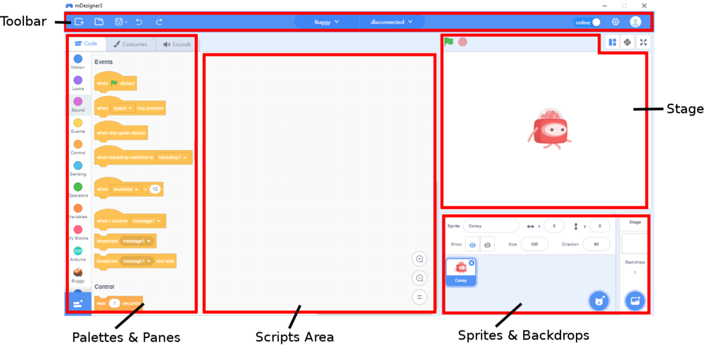
Here is a quick overview of mDesigner's User Interface. A more in-depth description can be found here. |
Toolbar
The Tool Bar in mDesigner provides many useful functions and configuration options.
- New Project - creates a new blank project.
- Open Project - open a saved project.
- Save / Save As (arrow) - save / save as the current project.
- Undo - undo the most recent change int the project.
- Redo - redo the most recent undo in the project.
- KIt - select the current Microduino kit being used.
- Serial Port - select serial port that the Microduino hardware (mBattery / mCenter+) is connected to.
- Mode Selection - select different usage modes for mDesigner.
- Online mode - control Microduino hardware in real time using mDesigner blocks. Microduino hardware requires a constant connection to the computer running mDesigner in order to function.
- Offline mode - complies and uploads script onto Microduino hardware. Microduino hardware can be ran independently without a computer after the script has been compiled and uploaded.
- Settings - change settings for mDesigner such as switching languages, help, updates, issue report, and about the program.
- Account
Stage
mDesigner (based on Scratch) can be though as a school play. The Stage is where the viewer sees the play. Sprites can be thought as actors or characters in a play. The Backdrop is the background. Together they make the Stage. Below is a quick overview.
- Green Flag - when clicked, all (When Green Flag clicked blocks activate).
- Stop Sign - when clicked, stops all blocks that are running. Blocks that are running have a yellow "glow".
- Sprite - sprites can be thought as actors or characters. There can be multiple sprites on the Stage. It is possible to customize unique sprites.
- Backdrop - is the background of the Stage. There can only be one backdrop active at a time. It is possible to customize or create backdrops.
The Stage includes Sprite(s) and a Backdrop.
Sprites & Backdrops
This section allow selecting, editing, or creating sprites and backdrops. Selecting a sprite or backdrop is done by clicking on it from this section.
Palettes & Panes
This section of the interfere contains the Sprite Pane, Costume Pane / Backdrop Pane, and Sound Pane. Switch between the panes by clicking on the appropriate tabs.
Script Pane
The Script pane contains the tools needed to make sprites and backdrops to do things. A Script can be thought of as the instruction your sprite or backdrop follows. Similiar to a school plays' script which instructs the actor what to do.
- Blocks - Blocks are instructions for sprites and backdrops to follow. There are many blocks each with their own type. Blocks are categorized into different categories based on their functionality or purpose.
- Block Categories - Blocks are sorted into different categories for quicker access and organization. Each category has its own color and blocks contained within are the same color. For example, "Motion" blocks are all blue.
Script Area
The Script Area is one of the most important parts of the mDesigner interface. It is the place to create and assemble the script for the currently selected sprite or backdrop. Dragging a block from the "Script Pane" into the "Script Area" duplicates that block into the script. Each sprite or backdrop has its own personal "script area". A script can be thought of as the instructions that your sprite or backdrop follows.
Configuring mDesigner for Itty Bitty Buggy
|
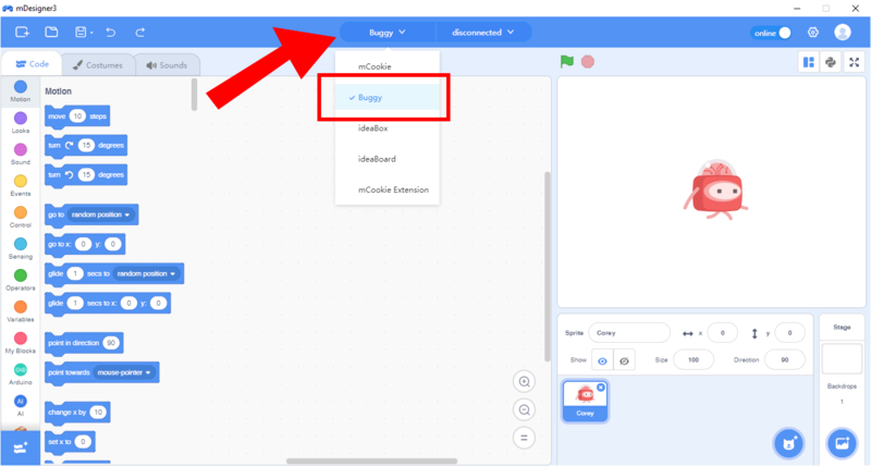
Under the kit selection, select Buggy. |
|
This allows access to the Buggy control blocks. |
Connecting to Itty Bitty Buggy to mDesigner (Online mode)
|
Ensure Itty Bitty Buggy is connected to your computer with the USB cable and powered on. |
|
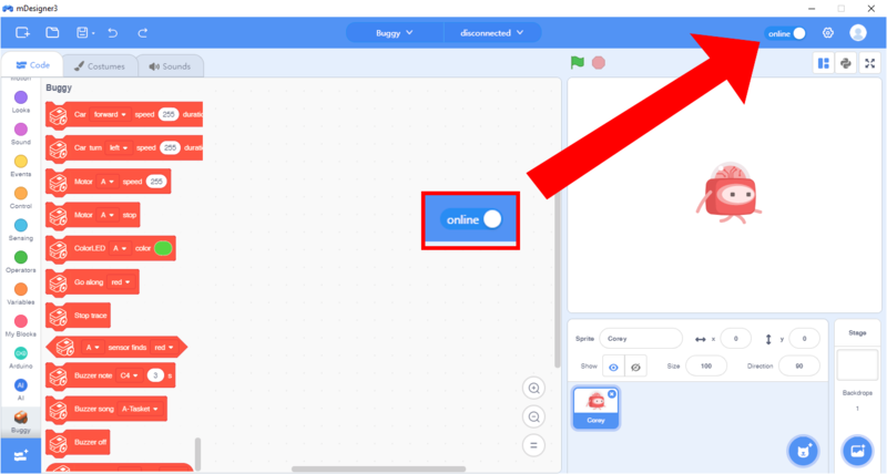
Ensure mDesigner is in Online mode. (If mDesigner is in Offline mode, click on the slider to switch it to Online mode.) |
|
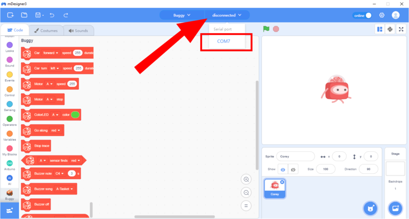
Click on the Port Selector. This will list serial devices connected to your computer. |
| Windows | Mac OS |
|---|---|
| Port will be listed as COM__ (w/ a number). | Port will be listed as /dev/tty.SLAB_USBtoUART |
|
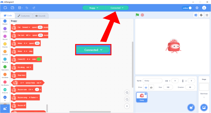
Click to select the port. The text box will now change from disconnected to connected (or ready). |
|
Note: If you do not see any ports or similar ports, please check if Itty Bitty Buggy is connected to your computer and turned on. |
|
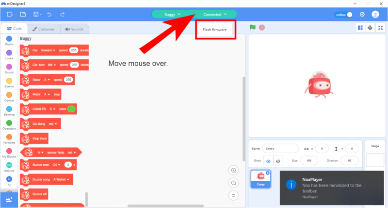
A special program needs to be uploaded onto Itty Bitty Buggy in order to use it with mDesigner in Online mode. |
|
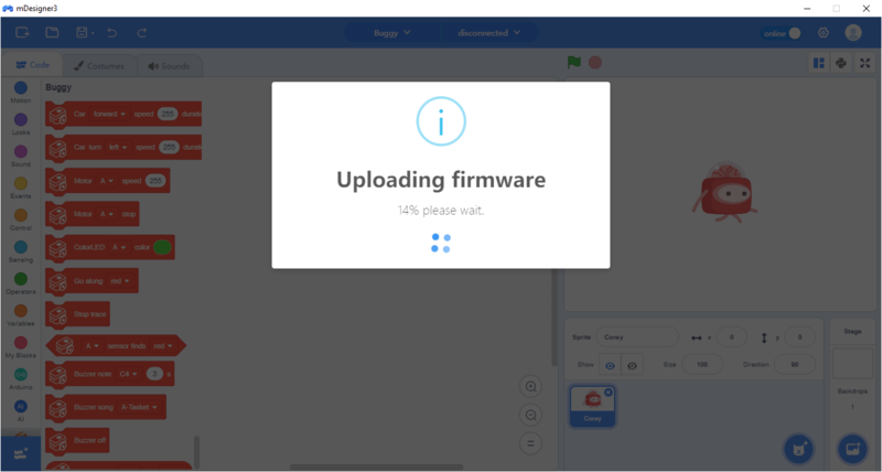
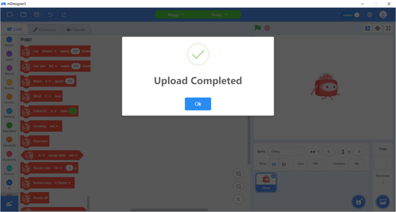
An upload dialog will appear and Upload Completed will appear when done. Click OK to close the dialog. |
|
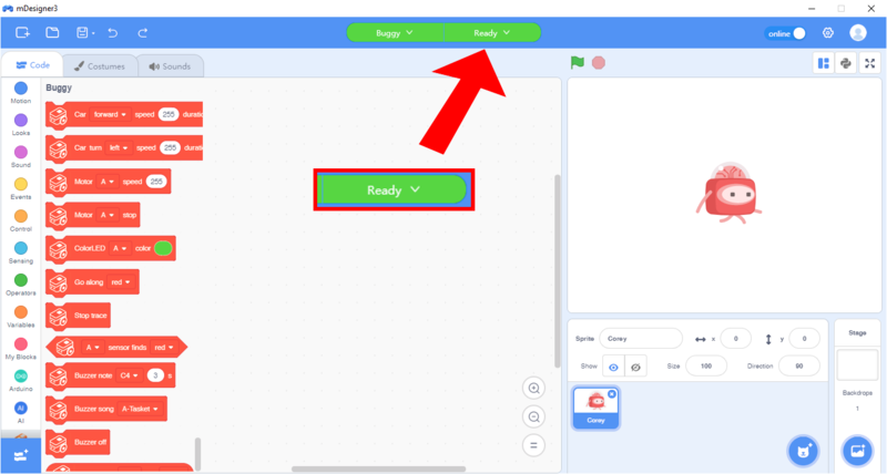
The Connected text will now change to Ready. |
|
Note: The text on the port selector determines the current status of Buggy's connectivity to your computer.
|
|
Itty Bitty Buggy is now connected and ready to be programmed in mDesigner! |
Assembling A Program
To create a program in mDesigner. Simply drag blocks from the Blocks section into the Script section.
First Example
|
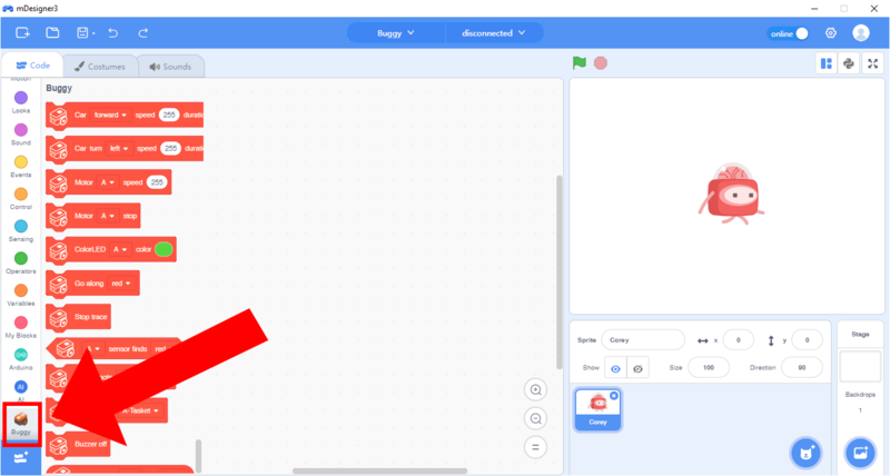
Clicking on a Block Category such as Events or Buggy will bring up the Blocks in that category. This allows you to quickly find the Blocks you need. |
|
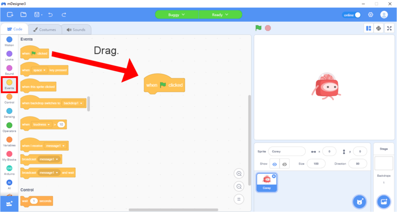
For this example, first click on Events under the Block Categories section.
Then drag the |
|
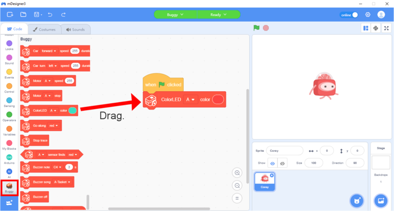
Next, click on the Buggy category. |
|
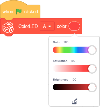
Now, change the color on the |
|
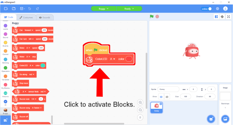
Click anywhere on the assembled code Blocks to run it. |
|
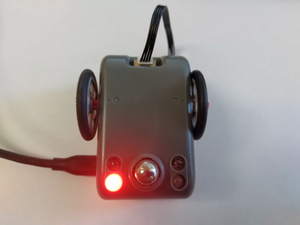
After activating the code Blocks, ColorLED "A" on Itty Bitty Buggy will turn on! |
|
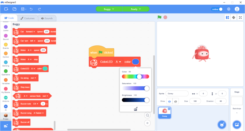
Select a different color, and activate the code Blocks again. What happens? |
"Online" vs. "Offline" modes
|
mDesigner can operate in two different modes: "Online" and "Offline" modes. In the example above, "Online" mode was demonstrated. |
mDesigner can interact with Itty Bitty Buggy in two different modes. Each mode has its own pros and cons. It is recommended to use Online mode initially before exploring Offline mode.
Online mode is Scratch, but with added blocks which are designed to interact with Itty Bitty Buggy and Microduino modules. This means the user has access to the stage and actor blocks. Projects (hardware, such as Itty Bitty Buggy) need to be connected to the computer running mDesigner. mDesigner communicates with the project (hardware), namely the Core+ module (embedded inside mCenter+), in "real time" over the USB connection by sending commands for the Core+ module to perform. This means that "Online" mode requires a constant connection with the computer running mDesigner.
Offline mode acts as a "visual" drag and drop coding editor. The script (code) is converted to "Arduino" (text code) code and then compile and uploaded to the attached the Core+ module (embedded inside mCenter+). This means that code can run even when detached from the computer. The stage and actor are disabled in this mode since the code runs independent of mDesigner.
| Capability | Online Mode | Offline Mode |
|---|---|---|
| Drag & Drop programming | Yes | Yes |
| Supports Microduino modules | Yes | Yes |
| Stage and actor enabled | Yes | No |
| Real time code testing | Yes | No |
| Code compiled and uploaded | No | Yes |
| Can run WITHOUT being connect to computer | No | Yes |
Communication Overview (Online Mode)
The communication between mDesigner running on a computer and the project (hardware) is outlined below.

| ||
| Computer: Computer running mDesigner sends commands or receives data with mCenter+ over USB. |
mCenter+: mCenter+ acts as a communication bridge with the Computer (running mDesigner) and the Core+ module. |
Core+:
|
Connected to Computer Requirement
In this mode, to control the modules, the user will need to have their project (hardware) connected to the computer sending commands in real time.
| Note: If the project (hardware) is disconnected from the computer running mDesigner, then the project (hardware) will stop receiving commands and thus does nothing. |

| ||
| Computer: Computer running mDesigner cannot send commands or receive data with mCenter+ over USB since it is disconnected. |
Core+: The Core+ module is no longer receiving commands and does nothing. | |
Programming Overview (Offline Mode)
The programming of a script (program) is outlined below.
| Note: After uploading the compiled code onto the Core+ the project can be disconnected and can run independent of the computer and mDesigner. |

| ||
| Core/Core+: Compiled script (program) is programmed directly onto the Core+ module and can run independently of a computer and mDesigner. | ||
