Itty Bitty Buggy: Example 4: Parallel Parking (mDesigner)
Contents
Introduction
Itty Bitty Buggy is great at tracing lines and even avoiding lines, but what about parking? In particular, parallel parking... this example will program Itty Bitty Buggy to parallel park!
Overview
In real life, parallel parking takes a practice to perform. This involves judging the distance of the parked cars & how to maneuver the car into position to get into the parking spot. More can be read about parallel parking here: https://en.wikipedia.org/wiki/Parallel_parking
Since, Itty Bitty Buggy does not actually have eyes in order to judge the distance of the park cars. We will just simulate the behavior.
There is a limited amount sensors on Itty Bitty Buggy, we will need to make the best use of these sensors. We have two Color Detectors on Itty Bitty Buggy on the left side "A" and the right side "B".
We will use the Color Detectors to determine when to activate the parallel parking sequence, then again when we have successfully parallel parked to stop the parallel parking sequence.
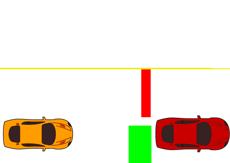
We arbitrary picked "red" to start parallel parking sequence and "green" to stop the parallel parking sequence.
A sample generated map is as follows:
Behavior
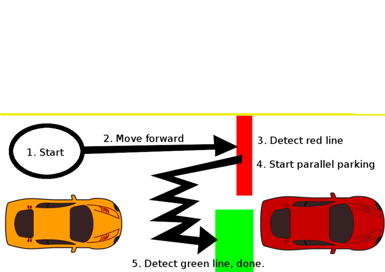
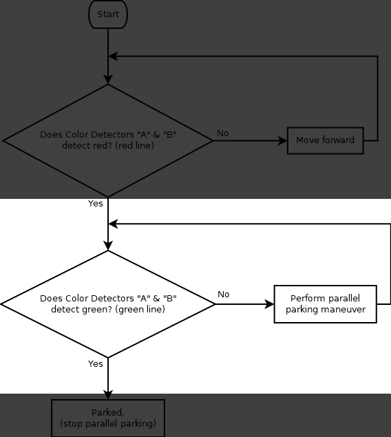
For this example, we want the following sequence of events to occur:
- Starting position of Itty Bitty Buggy.
- Itty Bitty Buggy moves forward.
- Itty Bitty Buggy detects a red line on both Color Detectors "A" and "B".
- Start the parallel parking. This is a constant loop of motor speeds which results in Itty Bitty Buggy slowly inching into the parking position.
- Itty Bitty Buggy detects a green line on both Color Detectors "A" and "B". Buggy is now in the parking stop. Stop the parallel parking.
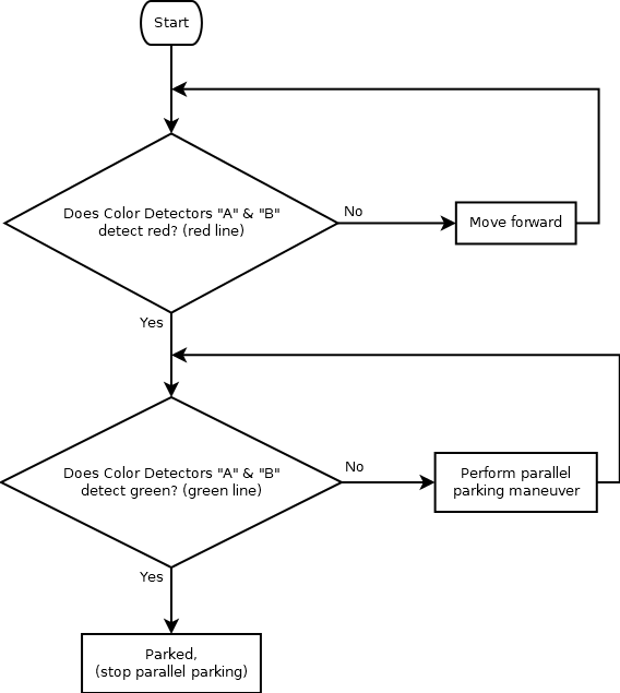
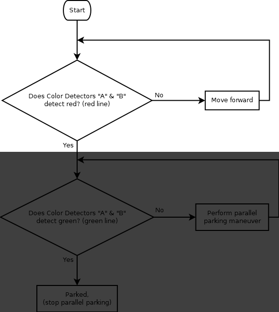
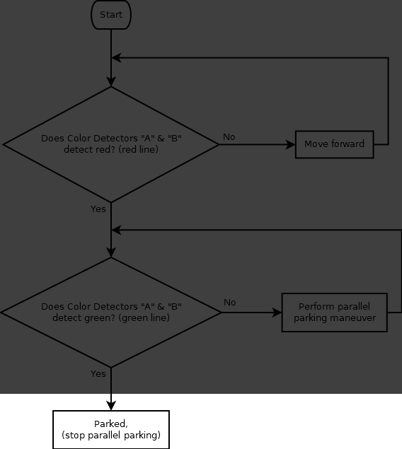
We can create a flowchart of the logic for this example
Assembling the Code
It is good practice to first create a flowchart of the logic of the program then translate it to code.
Creating a flowchart prior will allow you to work out the logic and behavior before coding.
How can we translate our flowchart into code?
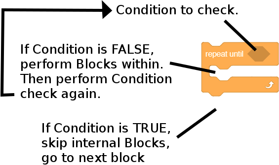
The Repeat Until block
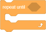
First we need to learn about an important block for this project. It is the Repeat Until block.
A simple explanation of how this block works is as follows:
|
|
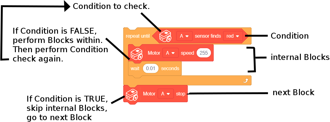
An example of using this block.
|
|
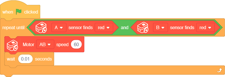
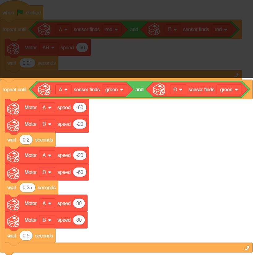
Assembling the first part
With this knowledge, we can now assemble the first part.
|
|
|
Assembling the second part
|
|
|
