The Use of DC Motor
From Microduino Wiki
Revision as of 08:08, 29 October 2015 by 1304410487@qq.com (talk) (Created page with " {| style="width: 800px;" |- | ==Outline== N20 direct current speed reduction motor: Compared with the ordinary DC motor, it is equipped with gear speed reduction box, which o...")
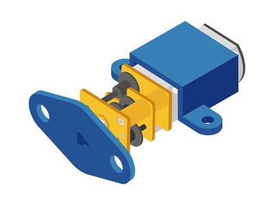
ContentsOutlineN20 direct current speed reduction motor: Compared with the ordinary DC motor, it is equipped with gear speed reduction box, which offers lower rotation rate and larger torque, enhancing the use rate of the DC motor in the automation industry. SpecificationSpeed Reduction DC Motor
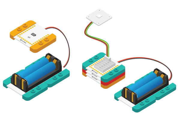
DevelopmentEquipment
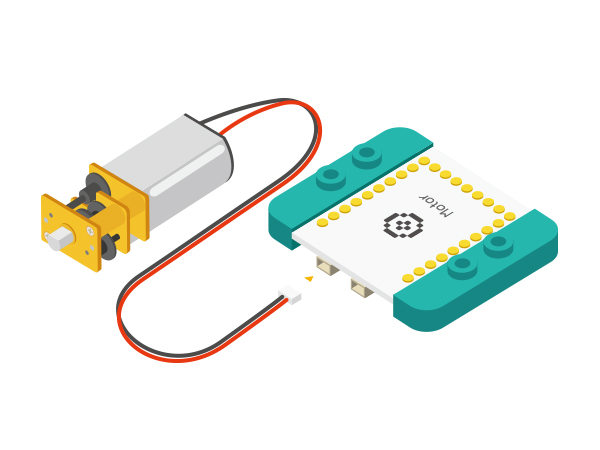
Wire Connection of DC Motor
//(D6,D8) controls (1A,1B) motor
#define OUT1A 6
#define OUT1B 8
//(D5,D7) controls (2A,2B) motor
#define OUT2A
#define OUT2B 7
===Preparation
Experiment 1: Connection and disconnection control
#define OUT1A 6
#define OUT1B 8
#define OUT2A 5
#define OUT2B 7

void setup()
{
  pinMode(OUT1A, OUTPUT);
  pinMode(OUT1B, OUTPUT);
  pinMode(OUT2A, OUTPUT);
  pinMode(OUT2B, OUTPUT);
}

void loop()
{
head();
delay(2000);
back();
delay(1000);
stop();
delay(500);
}

void head()
{
  digitalWrite(OUT1A, HIGH);
  digitalWrite(OUT1B, LOW);
  digitalWrite(OUT2A, HIGH);
  digitalWrite(OUT2B, LOW);
}
void back()
{
  digitalWrite(OUT1A, LOW);
  digitalWrite(OUT1B, HIGH);
  digitalWrite(OUT2A, LOW);
  digitalWrite(OUT2B, HIGH);
}
void stop()
{
  digitalWrite(OUT1A, LOW);
  digitalWrite(OUT1B, LOW);
  digitalWrite(OUT2A, LOW);
  digitalWrite(OUT2B, LOW);
}
=Debugging
Experiment 2: PWM Motor Speed Control
//( D6,D8) controls motor (1A,1B)
#define OUT1A 6
#define OUT1B 8
//( D5,D7) controls motor (2A,2B)
#define OUT2A 5
#define OUT2B 7

void setup()
{
  pinMode(OUT1A, OUTPUT);
  pinMode(OUT1B, OUTPUT);
  pinMode(OUT2A, OUTPUT);
  pinMode(OUT2B, OUTPUT);
}

void loop()
{
  for (int fadeValue = 0; fadeValue <= 255; fadeValue += 5)
    //Loop statement. Along with PWM rate increases, you can change brightness level by controlling fadeValue.
  {
    analogWrite(OUT1A, fadeValue);  //Write rate level into the motor
    digitalWrite(OUT1B, LOW);
    analogWrite(OUT2A, fadeValue);
    digitalWrite(OUT2B, LOW);
    delay(100);                       //Delay time of rate. (The unit is ms)
  }
  for (int fadeValue = 255; fadeValue >= 0; fadeValue -= 5)
    // Loop statement. Along with PWM rate decreases, you can change brightness level by controlling fadeValue.
  {
    digitalWrite(OUT1A, LOW);
    analogWrite(OUT1B, fadeValue);  // Write rate level into the motor
    digitalWrite(OUT2A, LOW);
    analogWrite(OUT2B, fadeValue);
    delay(100);                     // Delay time of rate. (The unit is ms)
  }
  delay(1000);
}
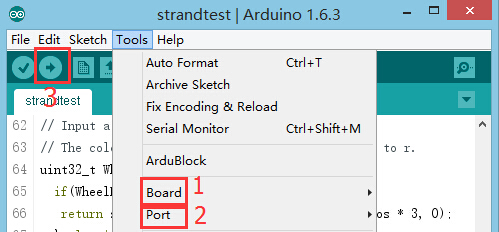
Program Debugging
Video |


