Microduino NRF communication-201KIT
From Microduino Wiki
| Language: | English • 中文 |
|---|
Outline
Bill of Materials
For ease of debugging and lowering the height of the module combination, here we need an extension board Microduino-Duo-V1. DocumentDebugging | |||||||||||||||||||||||||||
| |||||||||||||||||||||||||||
|
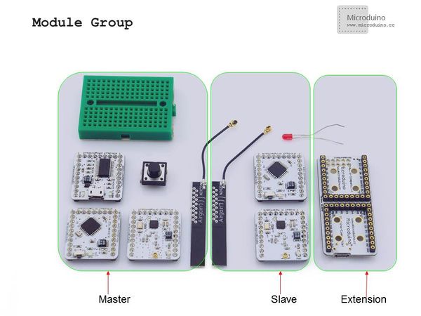
Prepare master module: Microduino-Core+, Microduino-FT232R, Microduino-nRF24, a button and a bread board | |||||||||||||||||||||||||||
|
Prepare slave module: Microduino-Core, Microduino-NRF24,Microduino Duo-V and an LED | |||||||||||||||||||||||||||
Button connection:Adopt internal pullup. (You need to define it in program.) | |||||||||||||||||||||||||||
|
The whole system picture: | |||||||||||||||||||||||||||
Download the program: | |||||||||||||||||||||||||||
|
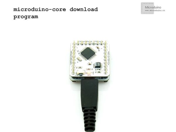
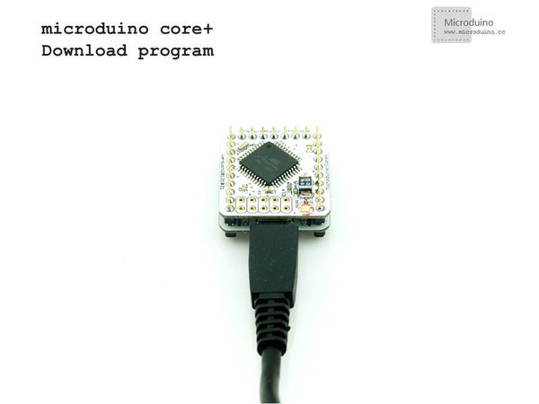
Choose "Microduino Core +(Atmega644P@16M,5V)" as the board of the master machine and "Microduino Core (Atmega328P@16M,5V)" as that of the slave machine, then download directly. ResultDownload the program to core board, press the button on master to contorl the LED on slave, light and off in turn.
Note
|


