|
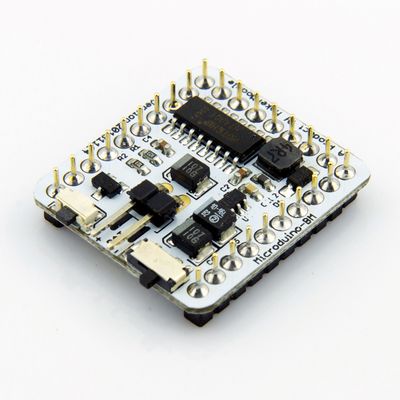
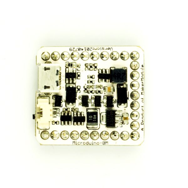
Microduino-BM is a discharging module which combines a single-cell Li-ion battery charge management,
power detection and LED indication. The output voltage is 5V, and LDO is 3.3V output, providing the outstanding battery management for the Microduino-Core module.
|
Features
- Support UPS;
- Integrate lithium battery charge/discharge management, power detection, 5v output, 3.3v LDO;
- Small, cheap, stackable, open;
- Uniform Microduino interface standard and rich peripheral modules, capable of having a fast and flexible connection and extension with other modules and sensors in accord with Microduino interface standard;.
- 2.54-pitch row female connector for easy integration into pegboards.
|
Specifications
Interface
- A two-notch toggle switch to control the output voltage (5v and 3.3v);
- A MicroUSB interface for power charging.
- A 1.27-pitch battery interface;
- UPIN27 contains the 5V, 3V3 and GND interface; (The analog voltage detection of BM can be selected between A6 and A7, and the digital low voltage will be output to D2 interface. Please don’t rely protection circuit to protect the battery, which only works in extreme circumstance. You can use mcu to detect the voltage of the battery and then judge the battery’s charge. )
|
Charging
- Plug in MicroUSB and charge the lithium battery with the current of 600ma.
- The indicator goes on when charging and goes out after finishing.
|
Discharging
- When you plug in MicroUSB, the 5v or 3.3v voltage is powered through MicroUSB. Otherwise, the voltage will be supplied by the lithium battery. Meantime, you need to pull the power output switch to “ON”. If it is not started, please plug in MicroUSB to activate and then try again.
- The indicator goes on when there is electricity output, otherwise, it goes out.
- 5V offers 1a electricity output and 3.3V offers 700ma output.
|
Low-voltage Battery Protection
| Undervoltage indication |
3.60V
|
| Low-voltage protection |
2.40V
|
| Indicator-off voltage when the voltage gets back. |
3.71V
|
Low voltage indicator goes on under 3.60V and when the voltage keeps decreasing to 2.40V, the lithium battery protection circuit works. The indicator will go out when the battery is powered to 3.71V.
Short-circuit Protection
When the output current reaches 1.2A, the lithium battery protection circuit starts and cuts off power supply. The circuit will be activated and get back to work only when you plug in MicroUSB to charge.
Efficiency of BM and Its Load Driven Capacity
100ma 5.05v output:
|
|
300ma 5.05v output:
|
|
500ma 5.05v output:
|
|
700ma 5.05v output:
|
|
1A 5.05v output:
|
|
|
|
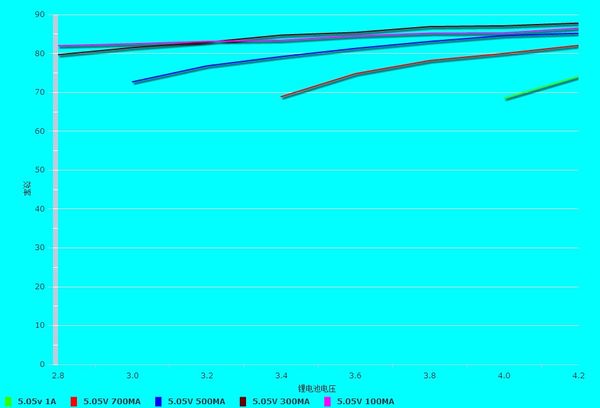
We can see from data above that BM’s 5v output shows excellent transfer efficiency no matter under low or high power output. The load driven capacity of that can reach 1A. The 3.3v transferring efficiency depends on the 1117 chip, which should be around 60% and the load driven capacity can reach up to 600ma.
Temperature Rise of System Operation
Temperature rise under 5v output and 30 ℃ indoor:
|
|
Temperature rise under 3.3v output and 26 ℃ indoor:
|
Documents
Eagle PCB 'File:Microduino-BM.zip
Main components
|
Development
- Battery: single-cell 3.7v li-ion battery;
- Recommended battery module is connected with 2PIN DuPont;
- Recommended power options: voltage 5V, current 600ma above, such as: computer USB, 5V phone charger.
|
Applications
- Lithium battery charge
- Lithium battery voltage boosting to power Microduino core modules
Pictures
|
FQA
History
November 14, 2013 new release, major improvements:
- Canceled VMOT pin, use the toggle switch directly and use the 5V port switching charge and discharge;
- Boost pushbutton can fully control the boost, UPIN27 the GND loop off.
- March 13, 2013 Batch completed.
- March 1, 2013 20130202 edition model released, testing is no big problem.
- February 2, 2013, using mobile power ASIC chip, re-layout.
- December 31, 2012, released the test panels, the main problems are:
- No 5V output;
- Battery Interface leakage;
- No power display.
|


