Outline
- Project:Microduino Sensor Dot Matrix
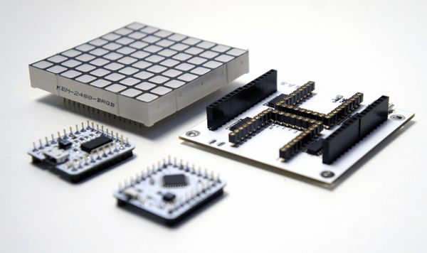
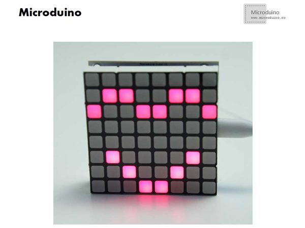
- Objective:Microduino Sensor Dot Matrix is specially designed for 8×8 full color matrix, whose size is 60.5*60.5mm. The length of each light hole is 5.0mm. Therefore, you need only three pins to control 192 lights, which can be combined into any color. Besides, the Matrix has PWM controlling function, capable of controlling the brightness.
- Difficulty:Middle
- Time-consuming:2 hours
- Maker:Microduino Studio-YLB
Bill of Materials
| Modules |
Number |
Function
|
| Microduino-Core |
1 |
Core Board
|
| Microduino-FT232R |
1 |
Download Program
|
| 5.0 Full Color Matrix Module |
1 |
Display
|
| The Drive Board of Microduino Sensor Dot Matrix |
1 |
Controlling RGB Matrix
|
| USB Cable |
1 |
Power Supply & Download
|
Documents
https://github.com/Microduino/Microduino_Tutorials/tree/master/Microduino_Libraries/RGBLEDMatrix
https://github.com/Microduino/Microduino_Tutorials/tree/master/Microduino_Advanced_Tutorial/Microduino_RGBLEDMatrix
Debugging
- Get Prepared:
- to download RGB LED Matrix program and then uncompress it to the libraries folder of IDE
- to download test program “Microduino_RGBLEDMatrix”
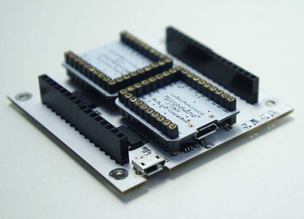
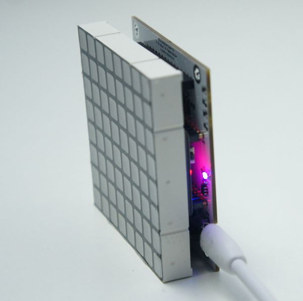
To build the circuit of Microduino Sensor Dot Matrix and fold Microduino FT232R and Microduino Core together on the drive board, and then fold the matrix on the board. Please note the pros and cons, which can refer to the flowing pictures.
Open the test program, you can see the experimental phenomena after successful compiling and downloading by choosing the right board.
m.clear();Clear the screen of LED Matrix ;
m.set_led_rgb(x,y,green,red,blue) Used to draw points
x: Horizonal coordinate
y: Vertical coordinate
green:0-255
red:0-255
blue:0-255
Result
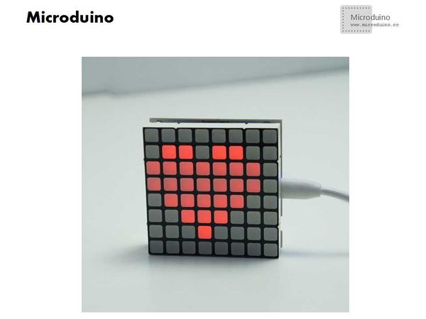
Microduino Sensor Dot Matrix can show assorted pattern and users can design more gorgeous color on their own demand.
Video
http://v.youku.com/v_show/id_XNzAxNTQyNDAw.html
| 