Single Color LED (use with mDesigner)
From Microduino Wiki
The Single Color LED is a light emitting diode (LED), which is capable of emitting a illuminating a single color. Red, green and yellow are the common colors. Support for this trinket is found in mDesigner.
Contents
Compatible Pins
The following pins on the Hub or mCenter+'s Hub support this module:
Hub
| Pin Name | Compatibility | Notes |
|---|---|---|
| Pin 0 | Yes | Not recommended, since Pin 0 & 1 are used by mDesigner (serial communication). |
| Pin 1 | Yes | Not recommended, since Pin 0 & 1 are used by mDesigner (serial communication). |
Blocks
Set Pin
This block sets the voltage level on the selected pin either to high or low.
- When set to high, the Single Color LED turns on (illuminates).
- When set to low, the Single Color LED turns off (no illumination).
Examples Uses
Software Setup for Examples
- Setup your software for either Live Mode or Arduino Mode.
Hardware Setup for Examples [[]]
- Example 1: Turn off the Single Color LED connected to pin 6.
- Example 2: Turn on the Single Color LED connected to pin 6.
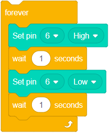
- Example 3: Turn on the Single Color LED connected to pin 6, wait 1 second, then turn off, wait another second, then loop repeatedly.
Set Pin PWM
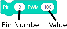
This block sets the voltage level on the selected pin varying values. Values between 0 and 255 will cause the Single Color LED to turn on at different levels.
- When set to 255, the Single Color LED is at maximum on.
- When set to 0, the Single COlor LED is off.
- When set to 127, the Single Color LED is half-way on.
- Other values between 0 and 255 will turn on the LED at appropriate brightness levels.
| Note: Only pins which support "Analog Write" will work correctly with this block. *For Microduino / mCookie Core: Pins 3, 5, 6, 9, 10, and 11 *For Microduino / mCookie Core+, mCenter+: Pins 7, 8, 9, 10, 12, 13, 22, and 23 |
-
- Pin Number - the pin to configure the state of. Note: Only certain pins support this ability. See above for which pins has this ability in your hardware setup.
- Value - the value between 0 and 255 to set the pin to.
Examples Uses
Software Setup for Examples
- Setup your software for either Live Mode or Arduino Mode.
Hardware Setup for Examples [[]]
- Example 1: Turn off the Single Color LED connected to pin 6.
(Note: Change the pin number to one that supports this block, see yellow box above)
- Example 2: Fully turn on the Single Color LED connected to pin 6.
(Note: Change the pin number to one that supports this block, see yellow box above)
- Example 3: Turn the Single Color LED half way on (127 out of 255 ~= 0.5) connected to pin 6.
(Note: Change the pin number to one that supports this block, see yellow box above)
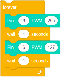
- Example 3: Turn the Single Color LED connected to pin 6 full on (255), wait 1 second, then set half way on (127), wait another second, then loop repeatedly.
(Note: Change the pin number to one that supports this block, see yellow box above)


